Navigation
Install the app
How to install the app on iOS
Follow along with the video below to see how to install our site as a web app on your home screen.
Note: This feature may not be available in some browsers.
More options
-
Congratulations waross on being selected by the Tek-Tips community for having the most helpful posts in the forums last week. Way to Go!
You are using an out of date browser. It may not display this or other websites correctly.
You should upgrade or use an alternative browser.
You should upgrade or use an alternative browser.
FAR Inertial Loads in MSC NASTRAN
- Thread starter Burner2k
- Start date
- Status
- Not open for further replies.
it depends on what you're modelling.
if a component, then 9g force distributed as would want (maybe a concentrated force at the CG, maybe a few "lumps".
if you're doing an aircraft and you've correctly modelled the mass then you can apply an acceleration/body force/inertial force ... the tricky bit (other than sorting out the units) is how to react this body force ?
if you model weights (instead of mass) then an acceleration/body force/... of 9 will accomplish what you want.
another day in paradise, or is paradise one day closer ?
- Thread starter
- #3
Hi RB1957,
Thanks for responding and I should have been more specific on my initial question.
Currently, I am hoping to model a simple interior monument say a small table subjected to FAR inertial loads.
Let me know if my interpretation of your response is accurate.
For modelling the individual parts of the component ("Table"), I could analyse as at static equilibrium i.e. use 9g distributed force or other options as loading conditions.
For the entire component with attachment (mainly to determine the interface loads), I could use inertial option.
Is my understanding accurate?
Regards,
- B
no, for a "simple interior monument" I'd apply the 9g load at the CG and that should be good for internal stressing and aircraft interface loads.
be careful how you constrain the table ... pinning each leg (4?) can lead to unnecessary and unreal reactions; fixing each leg is "right out !"
another day in paradise, or is paradise one day closer ?
be careful how you constrain the table ... pinning each leg (4?) can lead to unnecessary and unreal reactions; fixing each leg is "right out !"
another day in paradise, or is paradise one day closer ?
- Thread starter
- #5
Thanks RB1957. That helps a lot.
Could you please explain a little bit more applying a fixed support to each leg? Was unable to understand the words right out in the context.
Per a document I read on gama.aero, the monument attachments preferably needs to be on elastic foundation which the stiffness of the base structure reflecting the structure to which the monument is attached to. For example, if one of the top fitting is a tierod, its stiffness can be simulated using a spring element. Gotta read more...
Appreciate your help so far!
what some (lazy) people do is fully fix (ie constrain all 6 dofs) the supports of their model. this is IMO (and not IMHO) wrong, more so if they ignore the moments created.
some (slightly less lazy) people will hard pin the supports (ie constrain (ie infinitely stiff) X, Y, and Z). this can easily create redundant and unreal reaction forces.
the best (IMHO) approach is to support your model with finite stiffness in X, Y, and Z. i'll typically use a rod (in each direction) length 1in, area 1in2, E = 1E7. you can delete some of these reactions if your design frees that direction. you can play with the size of this stiffness, and see that other values have little affect on the results (actually, I'd encourage you to do this, do satisfy yourself that this is a reasonable modeling approach).
another day in paradise, or is paradise one day closer ?
- Thread starter
- #7
- Thread starter
- #8
Hi RB1957,
I am not sure if this is an issue. Anyways, here it goes.
I tried a simple table subjected to a distributed load. The loads were applied to represent 9g forward emergency condition. I modelled the table leg attachments using the approach you suggested. Three CROD elements in each direction.
The unattached end of CROD element was constrained in all 6 DOFs.
When I extracted the constraint loads in each attachment using 'Loads->Freebody->constraint forces' option...I can get axial forces but no moments. Is it normal to have no moment reactions in the attachments?
I realize CROD element in NASTRAN can carry just axial & torsional loads.
I hope I have provided enough info for the question to be answered. Please feel free to ask if more info is needed.
Thanks in advance,
- B
you constrained the rod fine, no probs. rods carry axial load only so each set of 6 constraints should be showing one force (yes?). of course, the easier way is to look at the rod loads.
another day in paradise, or is paradise one day closer ?
another day in paradise, or is paradise one day closer ?
- Thread starter
- #10
Hi RB1957,
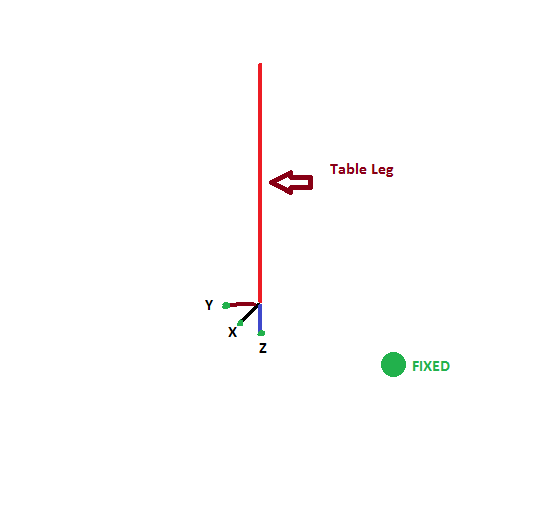
Thanks again for the response. I am getting a constraint force in 3 directions (X, Y, Z) in each attachment not 6.
As I mentioned in my previous post, the attachment is acting like a simply supported end fixity and thus no moments are being developed. (The bending stress is zero in the table leg towards the attachment end).
Here is how I have modeled the attachment. Would appreciate if you could please let me know if I have gone wrong somewhere in the interpretation.
stressebookllc
Aerospace
Burner2k, I believe you will find some useful information here:
Aerospace Stress Analysis and FEA Courses
Stressing Stresslessly!
Aerospace Stress Analysis and FEA Courses
Stressing Stresslessly!
the point of using rods is to get a pinned support on the model, with a finite stiffness (as opposed to a hard constraint).
The end of the rod (away from the model) is fully constrained (X, Y, Z; autospc RX, RY, RZ), the rod provides a stiff axial support to the model. maybe if you hard constrain the RZ you'll get some of this torsion.
another day in paradise, or is paradise one day closer ?
The end of the rod (away from the model) is fully constrained (X, Y, Z; autospc RX, RY, RZ), the rod provides a stiff axial support to the model. maybe if you hard constrain the RZ you'll get some of this torsion.
another day in paradise, or is paradise one day closer ?
- Thread starter
- #17
Bopeco,
Thanks for suggesting about Torsional Stiffness to CROD. I was totally unaware that J needs to be supplied to CROD. I assumed that Nastran will compute the J automatically from supplied area...but then again different cross-sections shapes can have the same areas...so J needs to be manually supplied. Just went through Nastran QRG.
I dunno as of now if the attachments behave like a pinned vs clamped...the "client" is suggesting to use CBUSH springs (or DOF springs based on need) and supply stiffness constants appropriately.
I appreciate the contribution made in this thread folks!
Regards
you can use a CBUSH and you should get the same result ... a finite stiffness instead of an infinite stiffness constraint.
IMHO, the CROD torsion is a red herring. Sure the ROD as torsion stiffness but we "never" intend to use it ... RODs are axial loaded elements.
another day in paradise, or is paradise one day closer ?
IMHO, the CROD torsion is a red herring. Sure the ROD as torsion stiffness but we "never" intend to use it ... RODs are axial loaded elements.
another day in paradise, or is paradise one day closer ?
- Status
- Not open for further replies.
Similar threads
- Replies
- 5
- Views
- 54
- Question
- Replies
- 31
- Views
- 186
- Replies
- 14
- Views
- 89
- Replies
- 4
- Views
- 54