Hi All. Greetings of New year.
I've been doing some fatigue hotspot stress analysis using 'International Institute of welding' (IIW) document 'IIW Fatigue Recommendations IIW-1823-07/XIII-2151r4-07/XV-1254r4-07 Dec. 2008'
and would like your inputs for below queries.
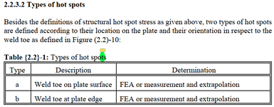
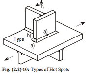
1) As per sec 2.2.3, there are 2 types of hot spot defined. Type a-weld on plate surface & type b-weld on plate edge. But the figure 2.2-10 seems confusing.


I have been using Type a only. For ex. column base plate

What does type b 'plate edge mean'? based on the figure 2.2, how are type a & type b different? explanation with figure would be greatly appreciated.
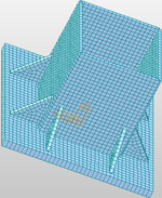
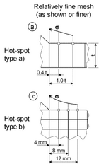
2) For type A, with fine meshing, extrapolation points are at 0.4t & 1t where t is thickness of plate element. Below are 2 cases with complete penetration butt weld(CPBW) & continuous fillet weld(CFW) cases. For CPBW, taking interpolation points from the joint & For CFW from weld toe. Please correct if this interpretation is wrong. elements modeled as per their designated thickness. weld is not modeled explicitly. Pls also advise if modeling can be improved for CFW case.


3) Consider below case. post is 140x5 CHS & arm is 150x9 SHS. so edge distance is 5mm as marked below.. For SHS arm 9mm thick, Hotspot stress contour 1t=9mm will not even fall on this edge distance. How do we approach HS in these cases?

Thank you for your time and inputs.
Regards
Sambhav
I've been doing some fatigue hotspot stress analysis using 'International Institute of welding' (IIW) document 'IIW Fatigue Recommendations IIW-1823-07/XIII-2151r4-07/XV-1254r4-07 Dec. 2008'
and would like your inputs for below queries.
1) As per sec 2.2.3, there are 2 types of hot spot defined. Type a-weld on plate surface & type b-weld on plate edge. But the figure 2.2-10 seems confusing.


I have been using Type a only. For ex. column base plate

What does type b 'plate edge mean'? based on the figure 2.2, how are type a & type b different? explanation with figure would be greatly appreciated.
2) For type A, with fine meshing, extrapolation points are at 0.4t & 1t where t is thickness of plate element. Below are 2 cases with complete penetration butt weld(CPBW) & continuous fillet weld(CFW) cases. For CPBW, taking interpolation points from the joint & For CFW from weld toe. Please correct if this interpretation is wrong. elements modeled as per their designated thickness. weld is not modeled explicitly. Pls also advise if modeling can be improved for CFW case.


3) Consider below case. post is 140x5 CHS & arm is 150x9 SHS. so edge distance is 5mm as marked below.. For SHS arm 9mm thick, Hotspot stress contour 1t=9mm will not even fall on this edge distance. How do we approach HS in these cases?

Thank you for your time and inputs.
Regards
Sambhav

