Continue to Site

Eng-Tips is the largest engineering community on the Internet

Intelligent Work Forums for Engineering Professionals

  • Congratulations MintJulep on being selected by the Eng-Tips community for having the most helpful posts in the forums last week. Way to Go!

Fault with delta (ungrounded) Source and Wye Grounded transformer 2

Status
Not open for further replies.

cuky2000

Electrical
Aug 18, 2001
2,133
Hello all,

We do have a 12 kV delta ungrounded source transformer feeding a station service transformer Wye/grounded via an underground 15kV cable rated for with 133% Insulation level . The selection of the cable insulation became a divided opinion in the event of ground fault as follow:

* Opinion 1: The fault will create essentially a corner delta generating only small current that may not be sufficient to trip the fuses. On a second ground fault, the associated fuses will blow up. This group recommend cable rated for 15kV and 173% insulation or 25 kV 100% Insulation to maintain the raised voltage for long term.

* Opinion 2: Other engineers believe that the current will be high enough to blow the 3-12 kV fuses and protect the feeder and transformer clearing the fault quick. Therefore, this group consider that the 15 kV cable with 133% insulation level is adequate for this application since will trip the fault in less than 1 minute.

All group concur if the load is a delta ungrounded transformer, the fuses will not blow up because the mall current.

please let us know your thoughts on this matter.
 
Replies continue below

Recommended for you

What, specifically, is the configuration of the station service transformer? Number of windings, connection of each winding, number of limbs on the core, etc. A nameplate photo would be great.
 
Dave,
1) Station service transformer: 300 kVA, 3 phase 12.47/120-240 solidly grounded (two winding)
2) Main Power Transformer: Auto-transformer, 3 winding, 230Y/69Y/12.47Delta.
See the enclosed file for additional details.
 
 http://files.engineering.com/getfile.aspx?folder=4ee0c49c-4b42-4eea-8544-047a866cd980&file=Cable_Insulation_for_Tertiary_Delta.pdf
That station service transformer will do its damnedest to keep the voltages where they should be until its neutral-ground bond burns up. Once the neutral-ground bond burns up the unfaulted phases will have phase-phase voltage to ground. The fuses will not blow until/unless there's a phase-ground-phase fault. It might happen in the station service transformer or it might happen most anywhere else. Bad news, stay away.

If I had to deal with that set up with no other options I'd add a three-phase gang operated interrupting device on the high side of the station service transformer with appropriate relaying.
 
I lived and worked for over 15 years in an area where wye/delta connections were common.
I was responsible for a small utility and it took me a number of years to eliminate the wye/delta connections. Then a number of issues went away.
That connection has the ability to transfer energy between phases. If the voltage on one phase is low, that connection will try to correct by taking energy from the other phases and back feeding it into the low phase.
If one primary line goes to ground, the transformer will transfer energy through the delta and back feed the fault at line to neutral voltage limited by three times the transformer impedance.
It is counter intuitive but the unfaulted phases will see the result of the fault current.
Yes the voltage to ground of the other phases may rise to phase to phase voltage.
With single phase fusing you will often see full voltage back fed to the load side of a blown fuse.
With single phase switching on the supply circuit it is common for one fuse of the bank to be blown.
The solution:
Use two single phase transformers in open delta. It works a charm and all the serious side effects go away.
I can and have written pages describing the action of the grounded wye/delta transformer bank under conditions of unbalanced voltages, a ground on one phase, one phase missing conditions, two phase missing conditions, etc.
Disclaimer:
My experience with the grounded wye/delta transformer banks was with three single transformer banks.
I anticipate the same issues with a three phase transformer with the addition of possibly lower impedance due to the phantom delta effect of a three legged core.
With a grounded source, the ground fault current will be the single phase fault current from the source plus energy from the unfaulted phases back fed through the delta winding limited by three times the transformer impedance.

To gain an understanding of the mechanism, consider an open delta on phase A and B.
For simplicity use a 13,000/7505 Volts grounded wye supply on the primaries and 240 Volt secondaries
The open delta will produce 240 Volts at the same phase angle as the missing C phase.
Now connect the secondary of a 7505/240 Volt transformer across the 240 Volt open delta.
The primary will develop 7505 Volts at the same angle as the missing C phase.
A fault across this transformer will cause a fault current at the angle of C phase but fed by A phase and B phase.
You can have a fault on C phase causing a fuse to blow on A phase or B phase.
Remove the fault.
By connecting the appropriate end of the primary winding to ground/neutral and the other end of the primary to the C phase source we now have a closed delta.
David summed it up well:
David Beach said:
Bad news, stay away.

Bill
--------------------
"Why not the best?"
Jimmy Carter
 
Dave/Bill: Thanks for your valuable advice.

Please help to visualize what happen with a SLG fault in the UG cable between the delta source and the station service transformer (Y-Gnd):

1)Does the CL fuses blow for a SLG fault?
a) If the fuse will not blow, are the cable exposed to operate phase-to-phase?
b) If only one fuse blow how the transformer behave with open phase?
c) For a second ground fault are the three fuses blow?


2) With the tertiary of main auto-transformer unloaded, will the transformer be at risk of been damage for overvoltage (ferroresonance, harmonic, etc).
 
ATP-EMTP even though it is designed for transient would give you an idea of how the system operates under different configurations.
 
If the fuse on the faulted conductor blows all of the fault current transfers to the station service transformer and its neutral-ground bond.

1)a) - As long as the station service transformer is able to supply current into the fault the voltages on the unfaulted phases will not fully reach phase-phase voltage to ground. Need to run the calcs to know how much it does raise.

1)b) - May not make much difference, the station service transformer can replace that voltage.

1)c) - Probably difficult to get beyond two blown fuses.

2) - Don't know.
 
Cuky2000 said:
Please help to visualize what happen with a SLG fault in the UG cable between the delta source and the station service transformer (Y-Gnd):
History:
I understand that North America was originally serviced with delta/delta systems.
After as loads grew, many systems increased the capacity of distribution circuits by changing to wye/delta configuration. That is when the strange issues unique to the wye/delta and the grounded wye delta connection became apparent.
In more than one old text book there is the note that a ground fault at one location may result in fuses blowing system wide.
Why:
With an ungrounded delta supply, when one phase goes to ground, there will be NO fault current.
The voltage to ground of the other two phases will rise to phase to phase voltage.
There may be a small charging current to ground due to the capacitive effect of the ungrounded phases.
Now add a wye/delta transformer. (Sometimes used as a grounding transformer.)
A fault to ground will now cause a fault current.
Consider a ground fault on C phase. The fault current will not be supplied by C phase of the supply. We have shown that.
The fault current will be supplied by the wye/delta transformer.

The fault current path.

The current path will be from the end of the high voltage winding of C phase of the wye/delta transformer through the cable to the fault location, through the fault to ground and returning through the ground to the grounded end of the C phase high voltage winding.
Where does the fault energy come from?
The 240 Volt secondaries of A phase and B phase form a 240 Volt open delta. This 240 Volts back feeds the secondary winding of the C phase transformer.
Hence the fault current for C phase is fed by A phase and B phase.
This leads to the paradox where a fault on C phase does not cause a fault current from the supply of C phase but rather causes a fault current on the two unfaulted phases.

This is a somewhat special case.
Normally the grounding transformer is in close proximity to the source transformer.
Here we are in effect considering a ground fault in the wiring between the supply transformer and the wye/delta grounding transformer.
However this is not unique. When the old systems were changed to wye/delta systems you had, in effect, grounding transformers distributed throughout the system or circuit.
You will always have the possibility of the line to neutral voltages rising to line to line voltage.
When considering Available Short Circuit Currents for a line to ground fault, you must add the contribution of the wye/delta transformer. It may be negligible or it may be significant. Do the math for each case.

Possible remedies:
1> Do nothing and live with the issues.
2> Float the wye point. Possible high voltage switching transients when the transformer is energized.
No problem after energization.
3> Add an impedance to ground and use an impedance grounded system. Easy to monitor ground fault currents.
4> Use two larger transformers in open delta. Works well with no issues.
5> Use a wye/wye or delta/wye transformer for 120/208 Volts or for 139/240 Volts.

What happens next.
We have a ground fault on phase C.
A fuse blows on an unfaulted phase. Let's use A phase.
Now the secondary of B phase is still energized and is still developing 240 Volts.
However we no longer have three phases, we are now dealing with a single phase condition.
The 240 Volt windings of A phase and C phase are now in series across the 240 Volts of B phase.
C phase is shorted and so the impedance is near zero.
The impedance of the A phase secondary will depend on the single phase load on A phase.
A phase will see a voltage of almost 240 Volts.
A phase will now develop almost full voltage on the primary and will back feed the system to the blown fuse. (And supply any single phase B phase to C phase loads.)
The current through the ground fault will drop to a value dependent on 240 Volts/12000 Volts or about 1/50 or 2% times the single phase load on B phase.
Currents will be low and there will be no further clearing unless this unique condition is detected and cleared by appropriate relaying.
B phase will remain energized and there will be lethal back feed voltages in places where we would not normally expect voltages.
Once again:
David Beach said:
Bad news, stay away.

Bill
--------------------
"Why not the best?"
Jimmy Carter
 
Respectfully
If the fuse on the faulted conductor blows all of the fault current transfers to the station service transformer and its neutral-ground bond.
That fuse will not blow. One of the unfaulted fuses will blow.
It's not often that we disagree.
I lived with these wye/delta systems for over 15 years.
Bill
--------------------
"Why not the best?"
Jimmy Carter
 
Bill Great explanation!

If is not much to ask, please help merging the practice with the theory. Enclosed is also a rough sequence diagram indicating the connection of the zero sequence open in the delta source but connected though the solidly grounded transformer.

For discussion purpose, let's assume that the solid conductor connected to the earth is large enough to continuous to operate with SLG on one of the phase conductor. Let's go over Bill's response to have better undertanding:
BILL's said:
1) With an ungrounded delta supply, when one phase goes to ground, 1) With an ungrounded delta supply, when one phase goes to ground, there will be NO fault current.
The voltage to ground of the other two phases will rise to phase to phase voltage. There may be a small charging current to ground due to the capacitive effect of the ungrounded phases.
2) Now add a wye/delta transformer. (Sometimes used as a grounding transformer.) 1) A fault to ground will now cause a fault current. (see the bubble on the enclosed zero sequence diagram).
Consider a ground fault on C phase. a) The fault current will not be supplied by C phase of the supply. We have shown that. b) The fault current will be supplied by the wye/delta transformer
.
For part 2-b, (SLG at the MV cable): is the fault supplied through the wye/delta transformer large enough to blow the CL fuses?
Can you see a problem allow the SST and the cable operate for long term with with an open phase after the fuse blow?
NOTES:
* Significant number of UG cable have been replaced in different facilities with this configuration. There is not indication replacing many SST.
* The operation procedure are not allow to disconnect the tertiary. The large main auto-transformer need to be fully isolated on the HV primary and secondary sides before replace the fuses or maintain the MV of the SST.
* One of the two SST transformer will be in standby disconnected from the ATS. Therefore 1 tertiary be unloaded for long term.
 
 http://files.engineering.com/getfile.aspx?folder=82f098ad-fd10-490d-8ff2-b8724ade70a5&file=Sequence_Diagram.pdf
So I did say "If"... ;-) Isn't that when a "tired fuse" gives out? I agree it's going to happen under any normal circumstances.


waross said:
That fuse will not blow. One of the unfaulted fuses will blow.

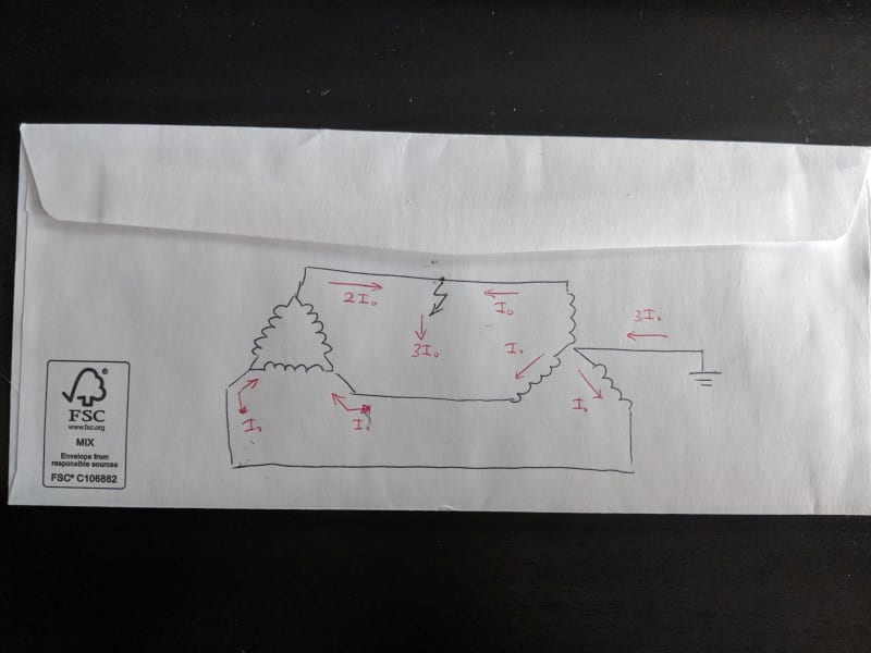
I suspect that the fuse on the faulted phase would act first, bearing in mind that the fuse is on the source side of the fault, not the transformer side of the fault. Below is my back-of-the-envelope (literally) sketch of the current flows in the 12.47 kV section, the fuses being located on the outgoing side of the tertiary delta (i.e., 2I0 current on the faulted phase vs only I0 on the two unfaulted phases).

sketch_oliand.jpg


I would also disagree with the placement of the "CL fuse" in the sequence diagram, which shows the current flowing through the fuse as I0, which is not correct (different currents will flow through the fuses on the faulted phase vs unfaulted phases) although I'm not sure how you would draw this as a sequence diagram. I'd probably work out the sequence currents without showing the fuses, and then calculate the individual phase currents based on these.

Cheers,
mgtrp
 
Perhaps the use of I0 to represent current was misleading--the ratios and direction of current were the key points. Below is the same circuit generated in ATP showing currents.

ATP_cfwzue.png


As an aside, this shows equal currents in each phase of the downstream transformer, so if this transformer had fuses (it doesn't in cuky2000's example) then in theory you couldn't predict which fuse would operate. In waross's real-world example, there is probably some load on the transformer secondary, which increases the current on the unfaulted phases and so one of these would operate first matching with what he has observed.

Cheers,
mgtrp
 
David Beach. My deepest apologies.
After years of coping with all the various issues with the wye/delta connection, the old memories kicked in and I overlooked the fact that this is an ungrounded source.
Now the first effect is that the voltage on the unfaulted phases will rise by 1.73, or line to line voltage.
The unfaulted windings may become saturated. The current will depend on the X:R ratios and the level of saturation.
The return current on the faulted phase will rise. Normally, with two phases loaded, the return current in the unloaded phase is equal to the currents in the loaded phases due to the phase angle displacement of the currents.
In the case of a shorted phase, the phase angles of the unfaulted phases change.
The return current in the faulted phase may approach 1.73 of the current in the unfaulted phases.
However this value is actually not that simple as both phases will not saturate at the same time.
Nevertheless, a higher than normal current but less than a fault current that is limited by the source impedance.
Will any fuses blow?
It depends. Transformer primary fuses are often greater than full load current rating to allow for inrush and overloads.
The fuses may or may not blow.
This is valid for both wye/delta and wye/wye transformer banks connected to an ungrounded source.

Second effect. with a delta secondary.
Feed through fault.
The ground fault on a feeder does not directly affect the current drawn from the source.
However, the secondary voltages will rise. The secondary open delta will no longer be true as the phase angles will be greatly changed. The secondary of the faulted phase will be subject to a significant overvoltage. (How much? See above, it depends.)
But the ground on the primary feed will be shorting the high voltage winding. This will cause a feed through fault current limited by the source impedance and three times the impedance of the transformer bank.
I erred previously in that I did not take into account the shift in phase angles of the return current.
On a distribution circuit the effects of single phase loading and other wye/delta banks on the circuit will have an effect.

The return current on the faulted phase will no longer be equal to the currents in the but will be greater.
The current will be greater on the faulted phase and the faulted phase may be the first fuse to blow.
It depends.


Bill
--------------------
"Why not the best?"
Jimmy Carter
 
So, back to this. Just did a bit of modeling, grabbed the tertiary (13.2, not 12.47kV) of one of our auto banks and added in that station service transformer. In that case I get a fault current of 720A, 240A per phase from the 300kVA transformer; two phases (240A each) passing through the tertiary and coming back on the faulted phase (480A), all 720A to the fault.

What's your CLF? What does it do at 480A. It probably isn't current limiting at that point.

What's the "fuse curve" of your 300kVA transformer look like? 240A per phase is over 18 per unit on the transformer base. What about that 720A up the neutral-ground bond, what does that "fuse curve" look like?

If the CLF blows the fault remains, the current stops flowing as there is no path back out of the delta. The faulted phase will be at phase-phase voltage to ground between the tertiary winding and the open fuse and at zero volts to ground on the fault side of the open fuse. The other two phases would be at about phase-neutral voltage to ground.

Much better to have a delta high-side on that station service transformer and use some form of 59N to monitor for the first phase-ground fault.
 
davidbeach has it spot-on with his modelling, analysis and final recommendation.

It's an ugly situation--either the CLF doesn't operate, and you're feeding the fault until something else burns up, or the fuse does operate and you're sending some screwball voltages to all of your station service equipment.
 
Another effect is the single phase effect.
With a ground on the wye point and on feeder phase C, and C phase supply fuse cleared, the A phase and B phase windings are now in series, line to line. The grounds have no reference to the supply delta so it is a single phase connection across A phase and B phase.
Each winding now sees 1.73/2 of normal voltage.
Together the secondaries are developing a sum of 1.73 of rated voltage.
That is being fed into the secondary of a shorted primary.
Then there is the effect of unbalanced loads on the secondaries which will effect the voltage division between the two transformers.
A serious unbalance may push one transformer into saturation.
Added to that is the effect of any running three phase motors which will try to develop and feed the shorted third phase.
All around, an ugly connection that is best avoided.
That said, the wye/delta is a good grounding transformer for an impedance grounded system.
I don't believe that accurate modeling of the currents is possible without information regarding the transformer saturation characteristics.
The load balance on the secondary may have an effect and motor induction generation will be a factor.


Bill
--------------------
"Why not the best?"
Jimmy Carter
 
Status
Not open for further replies.

Part and Inventory Search

Sponsor