Continue to Site

Eng-Tips is the largest engineering community on the Internet

Intelligent Work Forums for Engineering Professionals

  • Congratulations Toost on being selected by the Eng-Tips community for having the most helpful posts in the forums last week. Way to Go!

FEA Analysis of a pipe support

Status
Not open for further replies.

Janosik

Petroleum
Jan 15, 2019
7
Hi,

Good to be finally on the forum, used your advice a lot while at university and now I am happy I can join this professional environment.
I am writing in relation to a closed thread: thread727-431518
I am looking at the exact same scenario.
I have a client looking to verify catalogue support loads.
We can get into a long discussion on how this is unnecessary, and that the loads are in the catalogue etc, however I have been there, and the client is not giving up on it.
I have maximum allowable loads provided by the vendor, so I know what I'm aiming at.
I have set up a model in Ansys, but I cannot achieve that allowable, and they are not even remotely close.
I have verified my analysis conditions on a simple model, I am thinking it is constrained/loaded incorrectly as the values are so far out.
I have explored analysis without pipe modelled, however this deformed the straps unrealistically.
As the client deals with several pipe materials apart from steel (CuNi, GRE, HDPE) I have to take this into account.
I have modelled the support with pipe, and noticed that the pipe stiffness has big impact on the stress levels.
Also I found a screenshot of an Ansys fea model in one of the pipe suppliers catalogues, where the pipe is in the clamp:
Pipe_clamp_ansys_fea_dzeaxt.png

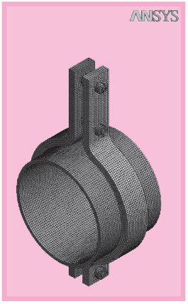
I understand this is not much of an indication, but I am garbing anything I can.
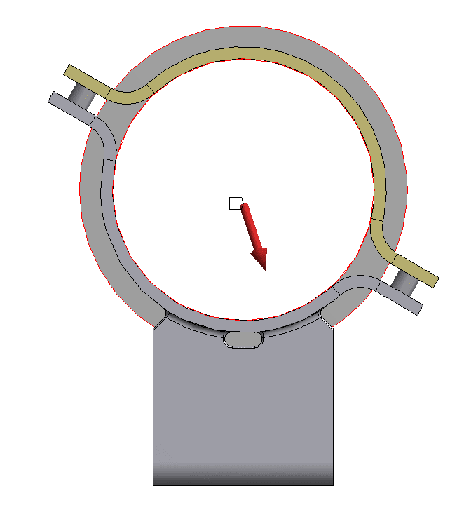
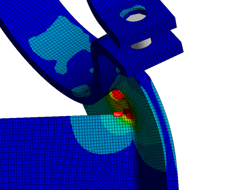
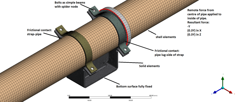
I have fixed the bottom surface of the clamp, added frictional contacts between pipe and clamp and applied a remote force on the inside surface of the pipe through the centre.
Please see attached for detail:
ansys_pipe_support_explained_pkyiug.png

So generally my question is: does anyone have any experience with pipe supports and the conditions on how to load them?
The way I am looking at it now sounds reasonable, however the results are blown out of the water, (around 10-15% of the catalogue values)
Any advice?
 
Replies continue below

Recommended for you

When modeling pipe as a shell remember to account for shell thickness in contact interaction.
I would also try modeling pipe as a solid. Everything else seems fine. At least when it comes to methodology. However you should also make sure that the load is apllied in the same way as it is in real life.
 
do you have any back-up for your catalogue allowables ?

Can you do tests ?

another day in paradise, or is paradise one day closer ?
 
Hi FEA Way,

Thank you for the prompt reply.
Shell thickness is accounted for, the thickness of the pipe is done on the inside.
I have ran the contact tool and after picking this up, I have made sure it is all ok.
I have used Solid before, just the computational times were a bit too long, so I am experimenting with shell.
I am applying the load using a remote force on the whole inside surface, transferred from the centre of the pipe:
Remote_force_hz6imm.png
 
rb1957,

Yes I have procured a support, and we have facilities to test it.
It's a fairly complex shape, so I'm not even sure where to place the strain gauges.
However first I would like to get my loads to be closer to the catalogue values.
I am more than sure my FEA is the problem, the loads I am receiving are far to low.
I am in contact with the vendor, however it is a slow process, they do not want to share too much, so not much backup, hopefully as of yet.
Thank you for the input.
 
oh, I thought you were the vendor and were trying to replicate the catalogue.

Instead you're the vendee, trying to replicate the catalogue without the background data/experience.

Don't understand why you disbelieve the catalogue ?

How are you distributing the load (from the CL) ? RBE3 ? Why not pressure applied to shell inner face ??

How is the model displacing ?
 
rb1957,

Yes, this is precisely what I am doing- "trying to replicate the catalogue without the background data/experience"
I do not disbelieve the catalogue, I have used these supports successfully for years.
I had countless conversation with the client about this he is fixed on "proving" the support can take the load.
I have analysed a pipe system, and extracted loads on supports, I then compared the loads to allowable from the catalogue, and job done? - standard practise.
Well I received a reply stating "this is not what we paid for, we could do this ourselves" etc.
So going down to business, the client paid for a verification and he is fixed on getting one, necessary or not.
I am distributing the load with a remote force, on the inside surface of the pipe, through the centre line of the pipe as shown two posts above.
I have used both RBE2 & RBE3, before I noticed the pipe material being a big factor I was using RBE2, now it is RBE3.
This is not an issue with pressure, pressure is within what the pipe and system can take, this is about dead weight, axial and transverse loading on the support.
Vertical down -Y component, for dead weight.
Transverse X component consisting of 30% of the dead weight.
Axial Z component consisting of 30% of dead weight.

 
ok, just trying to understand where you're at. Sounds like an overly fussy client ... so long as he's paying. I'd've thought your analysis would be the loads on the system supports (and the internal loads in the piping, then specifying components to handle those loads. But that's a different windmill (to tilt at).

are the clamps as open as shown ? there's no packing between the bolted flanges ?

where's the fitting failing ? Does the vendor have anything to say about your results ?

I'd suggest testing (simple for dead weight).

another day in paradise, or is paradise one day closer ?
 
Maybe I've missed that point in the text above, but what about first tightening the bolts, then fixing their new length and then adding the pipe pressure? Friction?

Is gravity with weight of the parts and the medium in the pipe relevant?

What about temperature changes and thermal expansion?
 
rb1957,

You are absolutely right, this is our standard process, so no tilting required.
Correct, there is no packer between the clamps, they are open as they are, connected through a simple beam and a spider node to the inside holes.
I had a look at bolt pre-tension but this did not make any difference, this is due to the direction of the load.
The full dead weight load is -Y, and then the two components are 0.3Y, so the resultant is mainly vertically down (-Y).
I explored analysing without the top straps, and it works! however it deflects the bottom strap, like the pipe would want to "roll off" the support, so the straps are only there to keep the pipe in place, marginal stress on the top strap and around bolt holes anyway.
The failure point is around this area, with the current loading:
fail_mivdzj.png

The turnaround with the vendor is not the fastest, so I did not get a comment yet.
Testing is an option, however I have used these supports for years, testing will prove the loads, however this is only for one size, and i have plenty sizes and pipe materials.
I am leaving testing to confirm my FEA when i manage to get any sense out of it.

Mustaine3,

As mentioned in this reply, bolt pre-tension was explored, and the straps are not the issue.
Pipe medium and weight are irrelevant, the support easily takes that, with the support spacing and weight per meter.
thermal changes will only make that worse, I was planning to look at that at a later stage, however it is not in any shape to be doing that now, it will only make it worse, and computational times are high as they are.
 
In order to deflect as shown in your model, the pipe would also have to bend, or the clamp would have to pull away from the pipe, but that is prevented by the bolts. You need to model the assembly, include the pipe, to get the correct deflections and stresses. Your model appears to only have 4 elements through the thickness, which may skew the numbers near those radii. What yield stress are you using, and do you assume any kind of strain hardening of the material in the area of the bends?
 
I meant why allow your client to say "that's not enough analysis" ? If SOP is to calculate loads and define components to take those loads, then going above and beyond is out-of-scope ? If he wants more analysis then he's paying for it.

If those clamps really don't have a spacer filling the gap ... boy, that's a pretty "cheap" clamp. I'd've expected that the gap is filled with something reasonably solid, to limit tightening around the pipe, to support the clamp, to look "not cheap".

Ok, you're pointing to a localised "hot spot". This is a linear FEA ? I suspect that this stress peak (or something like it) exists in the real part and that the real world allows this to happen without failure. Try running NL.

another day in paradise, or is paradise one day closer ?
 
Echoing rb1957 that nonlinear geometry and materials, if you're not using them already, will get you closer to reality. You've probably combed through the manufacturer's catalogue already, but I've seen others (I'm thinking timber supports but might be misremembering) that actually describe what they consider "failure". Some localized plasticity may not have been considered a failure.
 
btrueblood,

I should of mentioned that this is a scaled screenshot because on true scale the deflection is unnoticeable.
I have modelled the pipe, and done it as assembly.
I have tried both solid and surface for the pipe, solid worked fine, however computational times have been long.
Now I am exploring surface, but that opened a different can of worms with combining solid and shell elements, this is a learning curve for me and I am not that proficient with Ansys, hence I am here.
Ansys support is helpful in most cases, however I did receive an answer from them one time, when my model was disconnecting bonded contacts, and "exploding" stating "it is a graphical error" and to be honest, that is not very helpful.
I expected 4 elements through thickens to be adequate, computational times are through the roof anyway.
Increasing the number of elements might help, I agree, however now I am looking at a fundamental flaw, my loads come out as 10-15% of what they should be, a few more elements will not fill that gap.
If I run it at 1 element thick or using shell, except for higher stress concentrations, the loads are comparable, so if 4x more elements did not give it justice, more will not either.
Yield is taken from a standard the supports are made to, it specifies a general allowable, but also factors for compression, tension, bending, bearing and shear, and for this specific clamp it is around 140MPa.
I have not looked at strain hardening, I will look into this, thanks for the tip.

rb1957
I just love your persistence, you remind me of myself at the beginning of this project, and I agree.
I was arguing too long as at one point it got elevated and my director came down and said "just do it!" (no advertising there!), at this stage only throwing in the towel and admitting defeat would make it go away, and I do not want to go without a fight.
The clamps are not designed for uplift, if this happens we take 2x bases and mount them above and below, something in the line of this:
180_arrangement_wkge2h.png

We have torque settings for the clamp bolts, and the clamps are rubber lined to spread the pressure more evenly, ensuring pipe is not compromised.
I have non linear friction contacts, that's about it, I was afraid this would go this way, I need to brush up on non-linear analysis as I only done very simple models of such.

ChadV,
Non-linearity - got it! I will educate myself and come back when I have anything.
This is something i did consider - local yielding, the stress is high, and goes away when the point has yielded, but thats NL again.
failure is a valid point, as rb1957 mentioned earlier, I have no backup/experience and no failure criteria apart from a max stress allowable.

Thank you all for the useful input and your time, I will update you on my findings if this does not defeat me.
 
i think we've all looked at the crest of that hill and said "nah, not today" (ie this isn't a hill to die on"). I wonder what said boss will say when you're 100s of hours over-budget ? (push you up that hill ?)

so the clamps clamp (duh!) the pipe, compressing the rubber/elastomer gasket. how are you modelling this ? applying preload to the bolts (calc'd from torque), applying an enforced displacement ?? reacted by the pressure between the clamp and the pipe ??
then apply external loads (from the pipe)

what a science project !!

If you're using linear FEA and you have this localised hot-spot you "can" say that this is "just" localised yielding, since you aren't compromising the loadpath ... but an NL run would be better rationale. These loads are extreme design loads, right, not typical service ?

Not sure I understand why one of your fittings is good for load in only one direction ? Probably that's what the catalogue/vendor says ?? Maybe it's saying that the pipe can transfer load into the fitting by bearing on the baseplate, and that loads away from the baseplate (carried by the strap and the bolts) are not reacted ... ie the strap isn't man (or woman) enough to do the job.

another day in paradise, or is paradise one day closer ?
 
140 MPa is a pretty low stress for steel, it sounds like it has a built-in factor of safety? I'd expect even mild steel to have a 30-35 ksi yield strength in the area of the bends, if not more.

Can you apply just a guide surface for the faying surface of the clamp, i.e. allow translation of the bracket but (at least the edge of it) must translate only axially?

Other than the above, I would just be rehashing what rb said.
 
Different application, but ASME VIII-2 (for pressure vessels and the like) has what's called limit-load analysis. You define your steel as linear elastic up to yield then perfectly plastic after yield (although practically you'll need to give it a small post-yield stiffness for convergence reasons). Then you ramp up your loads until the model can no longer converge, which is the point of complete failure. The permissible load is that "limit load" divided by an appropriate factor of safety.

There are of course lots of other requirements for pressure vessels, but it seems to me that the spirit of this analysis might be helpful. Note however that assuming perfect plasticity means you won't get meaningful displacements, and it's entirely possible that the manufacturer's "failure" criterion could be a large gross deformation as opposed to material failure.

I hope that muddies the waters! This work sounds both fun and frustrating in equal measures, but make sure you don't get overcome by the "frustrating" part and forget to appreciate that you're getting the opportunity to do the kind of analysis that lots of engineers think about but never get to actually do!
 
Also Janosik, you mentioned bonded contacts "exploding" in ANSYS. I don't know your particular case and wouldn't cast shade on the advice of ANSYS tech support, but it's worth mentioning that bonded contacts can "break" in some cases, counterintuitive as that may feel. ANSYS defines a contact stiffness which is a function of the stiffnesses of the two bodies in contact. If one of those bodies is quite soft, then the contact can be quite soft. If you then have a force through the contact that causes a relatively large deformation, the two bodies can separate far enough that they're no longer within the pinball region that the program uses to determine whether contacts are closed. Once they're no longer within the pinball region, the contact is noted as "open" and no longer functions.
 
rb1957

I am not modelling the liner, I am interested in the stress of the base, dont think the liner will change that much anyway.
Yeah I considered this as localised stress and discard it, however I am unsure at what is the limiting factor?
How much is local yielding and how can I justify just that?
These are maximum operational loads, as stated by the vendor.
The load given by the vendor is dead weight only, however there is a statement where it accepts 30% of the dead weight in transverse/axial, this is standard practise.

btrueblood,

140 is quite low, but is is stated in black and white, at the moment the only value that will help me is 10x more... like that will happen.
I tried to load it in shear only, that's when I thought i might need to use symmetry and a longer flexible pipe with a series of supports to asses as a system, never got there as model too complicated.
When I load it only axially (limit displacement in vertical, the base starts to see tension in dead weight as it is elongating the base- totally opposite to what I am looking for.

ChadV,
I will have a look in ASME, apart from a value of "allowable stress" from a table I have no other failure criterion.
Vendor states the standard they use, so I think they are loading it differently? I don't know.
I am looking into the bonded contacts now, I am having a hard time combining shell.solid and now rigid elements... I think Ill just add a material with a ridiculous high stiffness.


I think the liner adds support to the flange, to how load is taken from the strap to the base.

If these are maximum operational loads, shouldn't there be some safety factor ?

If you want "truth", run NL (and model the liner and bolt preload). If you want a "story" (and there's not much wrong with that), get an author (someone experienced enough to tell the difference between a problem and a non-problem).

another day in paradise, or is paradise one day closer ?
 
Status
Not open for further replies.

Part and Inventory Search

Sponsor