Eng-Tips is the largest engineering community on the Internet

Intelligent Work Forums for Engineering Professionals

FEA Analysis 1

Status
Not open for further replies.

dbday

Mechanical
Jan 10, 2009
82
0
0
GB
Hi,
I have been looking at an FEA analysis of a pressure vessel that is to operate at 35,000 psi.
It is a spherical vessel and the FEA shows a stress gradient across the wall of the vessel from the id to the od, with the stress level exceeding the allowable value at the id, whilst at the od the stress level is quite low.
For the starting point I selected my initial wall thickness for the analysis by doing a simple ASME VIII vessel calc using PV Elite.
Is what I am seeing to be expected ?
Is an excessive stress level for the inner material ok, as long as the outer material holds good ok ?
Would I get cracking from the inside if we made this ?
Vessel id is 250mm, od is 650mm and material is carbon steel.

Any thoughts ?
 
Replies continue below

Recommended for you

That's quite a few questions that can't fully be answered without knowing more about your particular vessel.

From what information you've supplied and your comments about FEA/stresses you probably need a lot of guidance in that area. From the cursory vessel geometry you've provided (is the vessel a 200mm thick forging?) you're well into the realms of elastic-plastic analyses, is that what you're doing?

Without more details on the vessel geometry, the failure mechanism you're looking at, the locations you took stresses through, the load case etc... it's difficult to assist, but, as a generalisation, yes you can have stresses in your model that exceed the basic allowable and still maintain the required design margins. Question about stresses suggest you're looking at linear-elastic results which wouldn't be appropriate for this configuration (R/t = 0.625).

There's some explanation of pressure limits in the Scope sections of ASME VIII Div 1, 2 and 3 but I'm not exactly sure if there's a demarcation between Div 2 and 3, there's probably some overlap between all three. However, with an operating pressure of 35000psi you'll be best placed between Div 2 and 3 and your decision may be based on if you're in fatigue service; cracking...

As a minimum look through Part 5 of Div 2 or KD-2 of Div 3, but it sounds like you need a specialist in this area.
 
You're well beyond ASME VIII-2, and I think far into ASME VIII-3 with such pressures (roughly 2400 bar(g)). I have zero experience in either of these codes, but know (from all reading here on eng-tips, esp. TGS4's replies) that these codes should only be applied by engineers who are experienced with and have full understanding of these codes, and the mechanics behind the code. Based on your post, I have little doubt you have no idea at all. The best you can do is stay away from this vessel and hand it over to someone experienced in such designs..
 
JS - The initial guess was using Div 1 - yes inappropriate I know, but you have to start somewhere.

Ben - We are not experienced in the assessment of designs with elastic / plastic deformation so your guidance is appreciated.
The geometry is very simple, it is a spherical vessel with a spherical internal cavity.
Inlet/outlet are 3/8" I/dia nozzles ad are diametrically opposed.
As we were considering to make the whole thing from a forging (two halves welded together) the nozzles would be machined so as to be integral to the main body.

As you may appreciate from my questions this is not an area we are comfortable with as our designs usually operate down around the few thousand Psi mark so such questions don't arise, or are easily avoided. Please understand, the query here is mostly to try to start to understand some of the issues with such high pressures, work out where we need help, or even determine if we should simply avoid the job !!

I don't think fatigue cracking due to minor cycles will be an issue as the pressure variation during operation is less than 1% of the operating pressure, fatigue due to major (start/stop) cycles is however a good point and so I need to check the life requirements.

Time for the Div 2 books.
 
Please hire an expert in Division 3 design for this vessel. You are way beyond your level of competence. I'm afraid that even hiring an expert in Division 2 will likely not be able to assist you.

If this is a case of trying to decide whether or not to take such a job, my helpful advice would be to run, not walk, away.
 
My first question for said expert would be "what shape should this thing be to hold XX volume". I'm thinking surely a long tube would be more feasible than a spherical vessel (which, I'm thinking, would be 50% weld metal by the time you welded it!). Think gun barrels here.
If you're thinking of fabricating it, consider how you're going to pressure test it, that might get expensive, too. And something to be witnessed from far, far away.
 
JStephen,
I'd be saying the exact opposite. The stress in a sphere is half that in a cylinder (at least for lower pressure applications), so the material can likely be a lot thinner if he builds a sphere versus a cylinder.

For the size he's talking about, I think the concept of two machined half-spheres with integral nozzles isn't terrible. There would only be one weld in there.

That pressure though is beyond my experience, and I'd point them towards a Div.2 or Div.3 shop.
 
That's a 26" sphere with a 10" hole in the middle, 8" thick. By the time you welded two halves together...come to think of it, what with the forging and all, might be cheaper to build the whole thing up from weld metal like a 3-D printer.

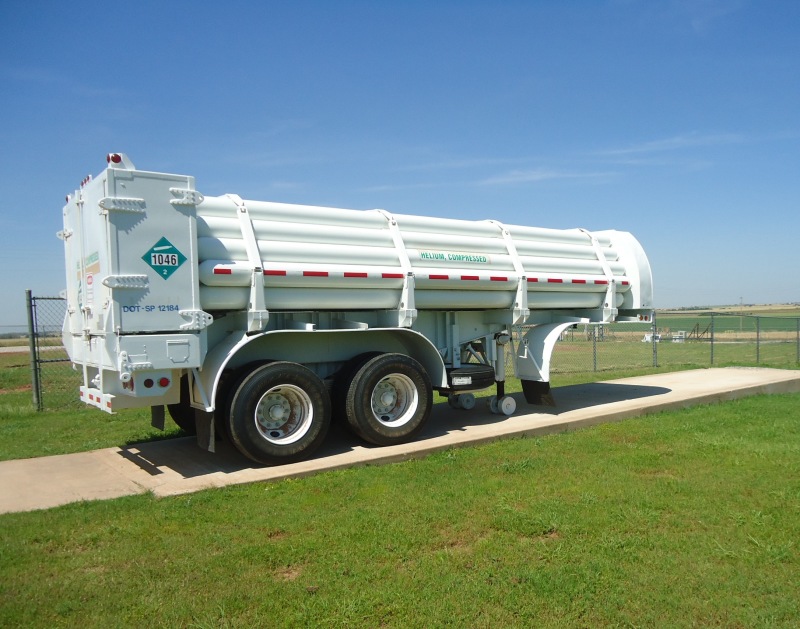
Theoretically, spherical vessels might be cheaper, in reality, that depends. So you wind up with stuff like this:
Helium_qot54w.jpg
 
JStephen
You wouldn't be recommending pneumatic testing for the proof test then ???

TGS4
Very sage advice, this is absolutely out of my ballpark, however, according to my customer it would seem that my competitor can run quicker than me !


I like the 3D printing idea, however I am not sure who would certify the whole thing as I don't think ASME have any rules in place yet for such construction, I know that Lloyds don't have a position as yet.

Thanks for the help / ideas / interest

 
JStephen,

I ran a quick Div.2 calc, and came up with a much thinner spherical shell: 19" OD / 10"ID - 4.5"thk. This doesn't take into account nozzle reinforcement, but this might make a sphere more reasonable.

The other consideration is what the purpose of the component is. Our shop built a much lower pressure sphere (3500psi / 16" dia) last year, which was a pulsation dampener. To get to the kinds of pressures the OP is talking about, you're normally running piston pumps or some other positive displacement pump. These types of pumps will be loading pulses of fluid into the system, which can put high stresses into the piping. A discharge dampener is used to even out the pulses, making life easier for the piping. A quick google search example: Link. For process reasons, these must flare to a larger diameter than the nozzles feeding the vessel. A sphere is often used to keep the wall thickness down.

Just some more food for thought...
 
I have worked on some piping systems from some HP compressors.
It was 40ksi design, 2" ID x 4.6" OD in material with UTS 140ksi min and design stress of 64ksi.

The previous design relied on autofrettage to survive. They would fab the pipe and then pressurize high enough to plastically yield the inner 25-30% of the pipe.
This is common practice in high pressure pumps, it may be useful for you. This is Div 3 work.

= = = = = = = = = = = = = = = = = = = =
P.E. Metallurgy, Plymouth Tube
 
Fabrication QA and technique is going to be as critical as design. Completing the design and then adding a little extra fatness "just to be on the safe side" will not be an option.
 
Status
Not open for further replies.
Back
Top