Continue to Site

Eng-Tips is the largest engineering community on the Internet

Intelligent Work Forums for Engineering Professionals

  • Congratulations IDS on being selected by the Eng-Tips community for having the most helpful posts in the forums last week. Way to Go!

FEA elastic region not following experimental

Status
Not open for further replies.

s57_s2k

Mechanical
Mar 6, 2018
9
Hello

I am trying to simulate uniaxial tensile test on 50mm gauge length stainless steel specimen on Abaqus. My problem is only in the elastic region it does not match experimental results, and the plastic region is 99% matching my experimental results. My model is explicit with Hex 8 node reduced integration solid element.

I have tried to manipulate young modulus ( stiffness E ) I have lowered it from 190 GPa to 160 GPa , but it did not change my FEA results which does not make any sense. What should I do ?
 
Replies continue below

Recommended for you

Does your analysis feature geometric nonlinearity (NLGEOM on) ? Did you try with full integration second order elements ? Did you check the results from Standard analysis ?
 
Maybe the experimental data is wrong. ?
You have not posted enough details to make any useful replies.
If changing the modulus does not change the load-strain curve you are doing something wrong.
 
"I have tried to manipulate young modulus ( stiffness E ) I have lowered it from 190 GPa to 160 GPa , but it did not change my FEA results"

What results ? Stress ?
 
NLGEOM is on , no I did not try full integration second order element , yes I have checked with implicit analyses it was very good in elastic region but at high strain before failure the analyses stops ( due to high non-linearity ). sorry I did not explain my self , when I say results I means pulling force vs elongation ( displacement ). From experimental test I have both ( stress vs strain ) and ( pulling force vs elongation ) graphs.

what I am trying to do is to make sure that my material data , boundary condition and my other inputs and method in general are correct to simulate spot weld under uniaxial tensile test with constant pulling velocity ( constant strain rate ).

At the moment both of my explicit simulation for 50mm length specimen sheet and single spot weld have problems in elastic region. I have even tried implicit analyses for spot weld but I got the same results as explicit in elastic region. I will post the results to be more clear , I will try full integration second order element now. I appreciate your help

 
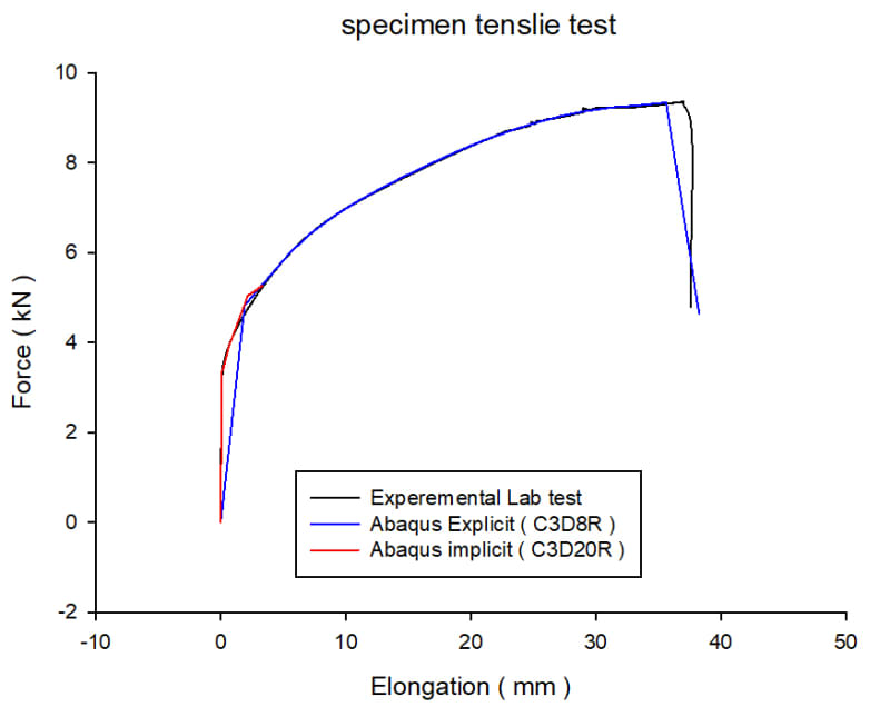
I have tried quadratic hexahedral element ( C3D20R ) using implicit analyses , now my results are excellent for specimen tensile test as shown in the pic here , I think my problem was I have to increase the number of elements through the sheet thickness or use a better element like ( C3D20R )

50mm_test_fegzsv.jpg


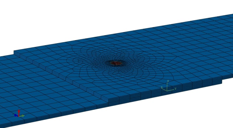
as for spot weld the results did not change ( in the elastic region ) when I tried quadratic hexahedral element compared to explicit analyses using C3D8R element ( I did not post the results for C3D20R standard element ) . For the spot weld I am using 3 element through plate thickness as shown in the pic

spot_111_r8kltg.jpg


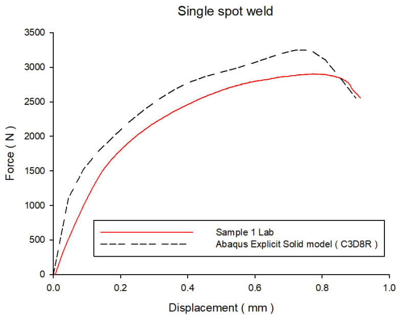
Lab_vs_Abaqus_1_m0e6s7.jpg


The results shows that my Abaqus model seems to be too stiff compared to lab experiment but I dont know why
. What should I do ? my stiffness E is 185 GPa this time when I changed it to 120 GPa the results didn't change much.
 
Solved the problem ,I made a new experimental test.
 
Status
Not open for further replies.

Part and Inventory Search

Sponsor