Continue to Site

Eng-Tips is the largest engineering community on the Internet

Intelligent Work Forums for Engineering Professionals

  • Congratulations MintJulep on being selected by the Eng-Tips community for having the most helpful posts in the forums last week. Way to Go!

FEA in Abaqus - paddle

Status
Not open for further replies.

Krzsiek2552

Mechanical
Aug 5, 2015
2
Hi.
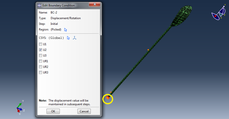
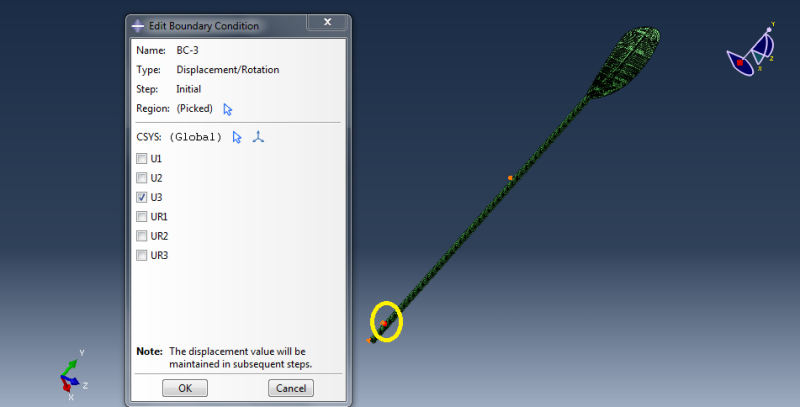
I need to carry out analysis of stress of kayak paddle. I'm sure that applied force is not to high because I found information about this in many articles. I applied the boundary condition as is shown in below.
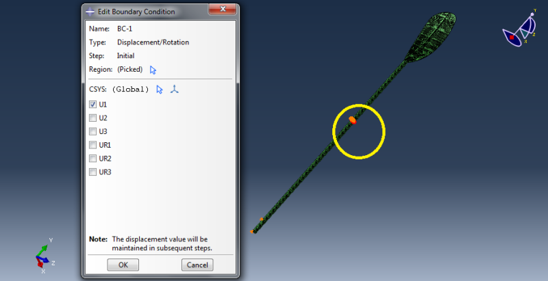
BC1_uby9gh.png

BC2_ssuprc.png

BC3_wdwgkj.png


The stress in the shaft is about 350 MPa while it should be no higher than about 120 MPa. Can anybody help me ? I will be really helpful as this is my MSc project and deadline is coming and I have no more idea what BC should I apply to obtain lower stress.
I attach also files needed to run this model in abaqus
 
Replies continue below

Recommended for you

I opened and ran your model and here are several of my thoughts.

1. Why 3 surface tractions instead of a pressure load on the paddle blade?
2. The 3 boundary conditions also seem like a significant oversimplification. Can you model the actual pivot point with contact and apply boundary conditions to this hardware?
3. When I ran your model the shaft peak stress was closer to 800 MPa.

I hope this helps.

Thank you.

Rob Stupplebeen
OptimalDevice.com
My Personal WP
 
1. Because I have carried out simulation in Ansys Fluent and from this code I have obtained force in x, y and z direction which acting on blade of oar during rowing. This kind of load is more reliable for my case than pressure and it is consistent with information from literature.
2. Yes, my BC are simplified. I have no idea how to simulate better the real condition during rowing. Do you have any idea ?
3. Yes, that true. What is more this stress occur in place where BC are applied. That's why I think that my BC are incorrect.
 
1. I would take the XYZ data and run your current model with a pressure load and see how close the ratios are. If they are close a pressure load seems to be much more appropriate.
2. To start with I would look at modeling it similar to a 3 point bend test. The 2 hands would be 2 of the points and the third would be replaced with the XYZ load. Contact will need to be modeled with friction and possibly global stabilization or contact stabilization.
3. The 2 hands could initially be modeled as rigid cylinders however you may want to evolve this towards industry tests or reality with hands.

I hope this helps.


Rob Stupplebeen
OptimalDevice.com
My LinkedIn
 
It looks like you're applying point constraints on the shaft so the stresses could be anything, and tending towards infinity when you refine the mesh further. If you're just looking at the stresses in the shaft then why even bother with FEA when a hand calculation will do. If you wanted to go to extremes with the hand calculation then consider a beam supported on an elastic foundation at the points where the hands make contact.

 
Status
Not open for further replies.

Part and Inventory Search

Sponsor