Continue to Site

Eng-Tips is the largest engineering community on the Internet

Intelligent Work Forums for Engineering Professionals

  • Congratulations IDS on being selected by the Eng-Tips community for having the most helpful posts in the forums last week. Way to Go!

FEA of necking/nosing (metal forming)

Status
Not open for further replies.

JTbearing

Mechanical
Nov 10, 2016
4
Hello,

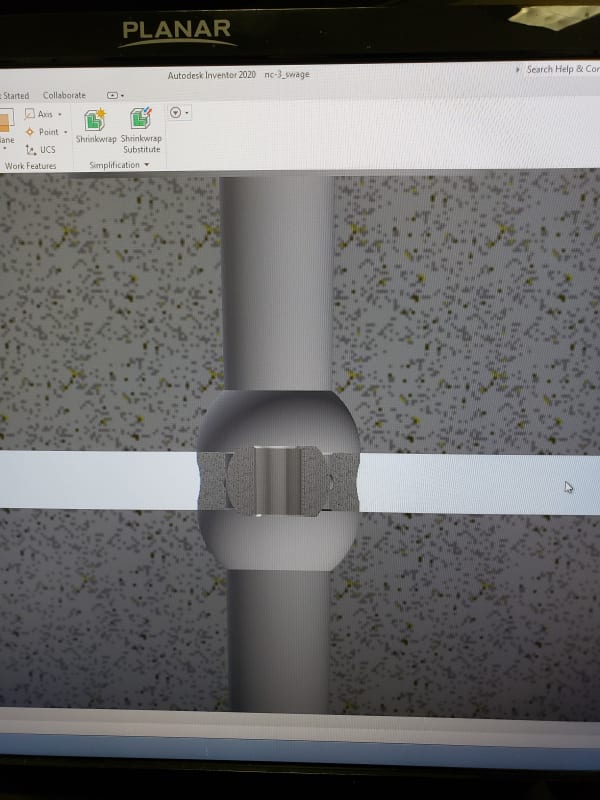
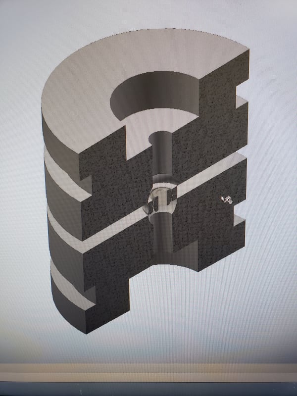
I was wondering if any one could help with this problem, this is a little out of my wheel house and have done some examples but it is hard to translate over to our product (spherical bearings). I am looking into using Inventor and Nastran In CAD to evaluate our necking process at my work. I'm not sure if the program would be capable to do it either or if there is a better option. We use Autodesk products so that's why we chose Inventer with Nastran. I modeled the spherical bearing and some necking dies but when the program runs instead of forming the outer ring around the ball it pinches the ring together and doesn't form at all. Is there an example that someone could lead me to or give some insight.

I have found research papers and things on this but have not found a good example to mimic. Here is a link to a image showing the process.

Thanks in Advance.


Replies continue below

Recommended for you

Please describe the settings of your simulation - boundary conditions, loads, interactions (including contact) and so on. Also show the screenshots with results if you can.
 
you need to run with material non-linearity, geometry non-linearity, and large displacements.

another day in paradise, or is paradise one day closer ?
 
Does Inventor with Nastran have the capability run a Nastran solution type that supports material non-linearity, large displacement or large strain, and contact?
 

Yes the nastran in Inventor has Non linearity and large displacement settings from what I can tell. I do know that the Nastran in Inventor replaced the Simulation Mechanical that was offered from Autodesk according to our rep. we talked to.

I was basically coping the Tutorial A1 from Autodesk and trying to modify it to work for my problem which might not be helping as much as i think.

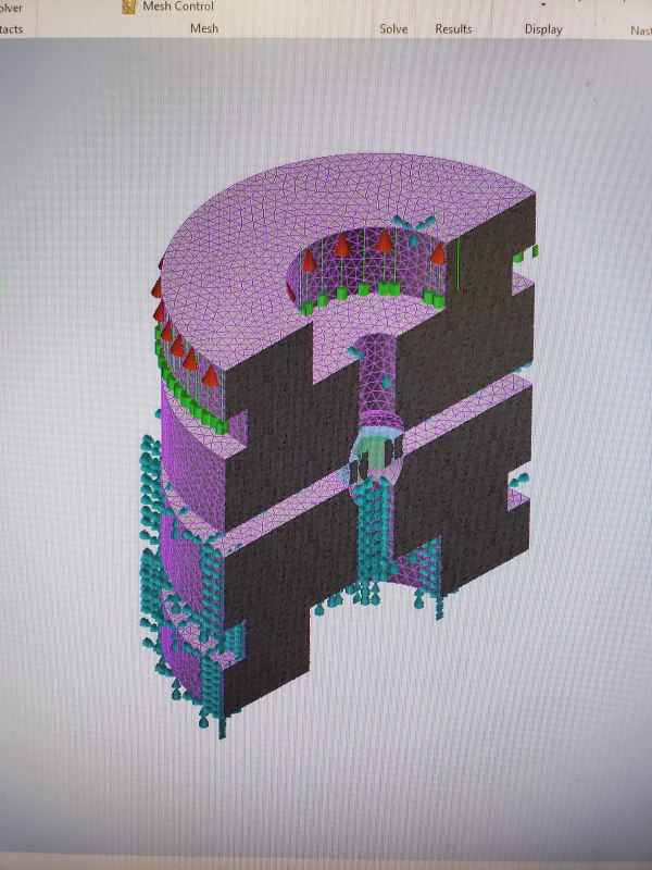
So currently the bottom die is constrained not move, the top die is constrained to only move in the X axis and has a enforced motion to move the top die on top of the bottom die. The ball I have fully constrained except it is also allowed to move in the X axis. The race is free to move in any direction but I did constrain it from all rotation (I did try it both ways and neither gave good results). I have surface contact between the race outside face and outside diameter to the die openings for top and bottom as two separate contacts (the race parts are the master entity and the die opening is the slave). Also, i have a surface contact between the race inside diameter and ball outside diameter (race ID is the master entity and the ball OD is the slave entity). For the surface contacts I'm not sure if the correct contact type currently i left it as separation.

I did look at my results and it seems the race isn't moving into the bottom die at all and the top die is only enacting the force. I was messing around with constraints at one point and did get the two race OD edges to pinch together at some point. I attached the picture of the current results.

Would the constraints from the inventor assembly be affecting it all?
 
 https://files.engineering.com/getfile.aspx?folder=94b4ed63-03aa-4c33-91a6-5e8adf60b8ae&file=20200324_132538.jpg
Constraints from CAD assembly are ignored in simulation, only boundary conditions matter.

Can you show more pictures of the model before and after the analysis ? It’s difficult to distinguish parts in the current picture.

Actually, you can make the dies and ball rigid if you only need results for the race.

The mesh definitely should be denser.
 
My company wanted to use the software to help alleviate the stresses on the ball and also help us when we put relief grooves in the outer ring to help the forming process and also once again alleviate the stresses on the ball.

I know I read about running the program using symmetry but I didnt want to do that until I figured this out a bit more.


20200324_142809_eof0q1.jpg
20200324_140915_dhz3o8.jpg
20200324_140904_xjwulw.jpg
 
In that case consider making the dies rigid. Maybe you could even simplify this to axisymmetric model. Such simplifications are very common in metal forming simulations.

Also note that the initial state of your model (with contact occuring only at the corners) may be challenging for the solver.
 
Status
Not open for further replies.

Part and Inventory Search

Sponsor