Continue to Site

Eng-Tips is the largest engineering community on the Internet

Intelligent Work Forums for Engineering Professionals

  • Congratulations MintJulep on being selected by the Eng-Tips community for having the most helpful posts in the forums last week. Way to Go!

Federal Electric Stab-Lok breakers 1

Status
Not open for further replies.

ScottyUK

Electrical
May 21, 2003
12,915
Federal Electric was a British company which appears to have been established to manufacture a home-market version of the Federal Pacific Stab-Lok miniature circuit breaker design built to the legacy BS3871 standard. Federal Electric are no longer trading.

We still have a fairly large population of early 1970's vintage Federal Electric breakers on site. I'm ultimately trying to replace these aging assets, but one of our inspectors has quite reasonably queried the breaking capacity of these early MCB's as we have some locations with higher-than-average prospective fault levels. Contemporary breakers have breaking capacities in the 1kA to 6kA range, but I'm struggling to find anything on the old Stab-Lok range. Has anyone got an old catalogue or old datasheet they could share?

I'm aware of the horror stories with the US-manufactured 2-pole devices not tripping, and I wonder if the problem extends to the 3-pole versions? There doesn't seem to be any discussion of that. FWIW, I think they're an awful design and I can well imagine that they do periodically catch fire in heavily loaded circuits.
 
Replies continue below

Recommended for you

The horror stories also extend to the single poles. FPE in the US was rigged and in the 70s most of their residential breakers bared a false UL label. Their commercial version at one point even had a replacement sticker warning users of defective breakers. Truthfully I know nothing about the foreign version, and I would be lying if I said I did, but in all honesty I would consider replacing it. Whose to say an official listing from 1970 guaranteeing 10ka Ics is actually 10ka Ics given the history? As is 40+ year old equipment isn't getting any more reliable as you know.
 
Thanks sn00ze,

These are a much, much earlier design. Black Bakelite housing, black toggle.

Some of the problems with the US-manufactured types of the same era are discussed in here: and in here:
I've already reached the conclusion that the UK-manufactured breed of these boards are absolute crap: the breakers are crap, the busbar structure is crap, the main switch is crap and the enclosure is crap. I'm just struggling to find out whether I have a problem with inadequate breaking capacity on top of the fire risk and failure-to-trip problem. Unfortunately I'm going to have some of these on our system for a while longer and I'd like to more fully understand what risk I'm faced with.
 
Truth is there is no way to know the real breaking capacity. It could be at, higher, or lower from a known listed value. Its a gamble in reality.
 
Hi Mbrooke,

Yes - I completely agree that the sooner these are replaced with modern equipment the better.

I'm looking for the original spec. because inadequate breaking capacity is a straight breach of legislation, and I have that situation on a couple of very old boards which will be replaced as soon as practicable. I may have the same problem on the Federal boards too.

Fair point that if FPE falsified their UL listing then there's no way of telling what else was falsified, like breaking capacity. It's come as a nasty surprise to read the history of these breakers.
 
Not sure if this will help. It has the US versions, but who knows, you might find a model listing that corresponds.


You need to make an account- it is free if the site is still like it was last time I used it (several years ago).

And yup, the history is not to assuring. Nor the design if you ever drill the US version open. They use a spring as the main fulcrum, for starters. [thumbsdown]
 
Oooh, I remember using that site years ago and had forgotten all about it. Thanks. :)

For anyone looking for information on the US versions, here's a couple extracts from vintage catalogues:


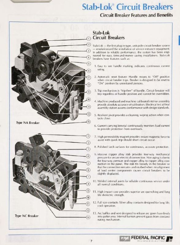
The British variant has a slightly different moulded housing but the main features of the US design are all visible. I'm going to dismantle one of ours and compare its internals with the sectional drawing in the second link.
 
Thank you for posting those, I've been looking for an old FPE catalog! :)


Drill a few open and post pics. They might be different they might not be. I think that will be the ultimate tell.
 
Mbrooke,

Some FPE catalogs available here to view, but you can only get them one page at a time (or I'm missing something obvious). If you're stubborn you can print it to PDF page by page and then stitch it back together. Not that I'd advocate such an act or anything. ;-)
I'll pick a couple of MCB's up next time I'm at site and open them up at home. Far too many hoops to jump through for Engineering to be allowed to use the pedestal drill in the workshop...
 
Let us know what you find, you are not the only one to inquire about foreign FPE.
 
We don't call them 'Federal Pathetic' without reason.

old field guy
 
Earlier post edited with link included.
 
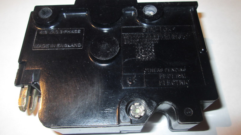
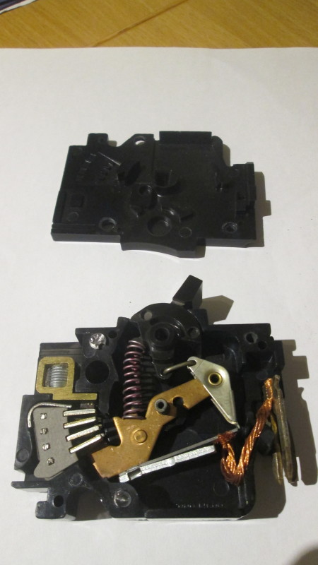
Well, I have opened up one of the British-made breakers and it is remarkably close to the US design based on the sectional diagram.


FPE_sectional_diagram_qfplzk.jpg


IMG_1572_rk0364.jpg


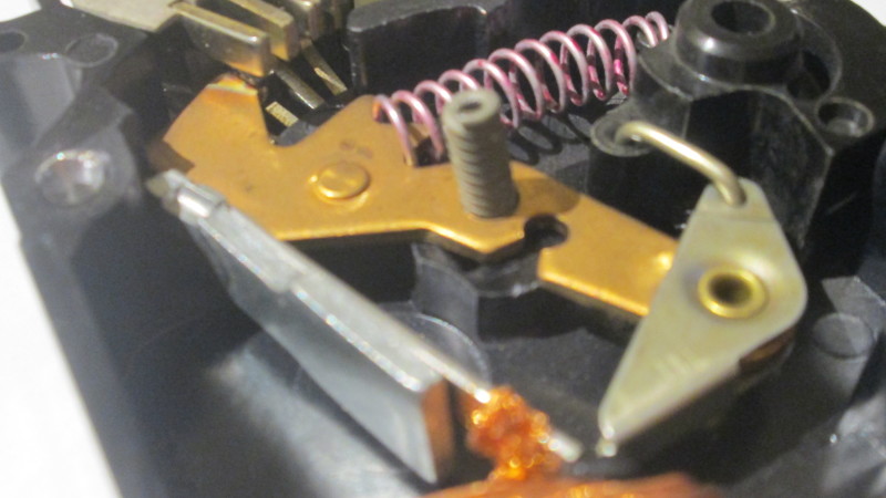
IMG_1575_mhidsg.jpg


IMG_1573_gwaarc.jpg


The pivot made from a spring, the plug-in Stab-Lok connector, and the trip mechanism are virtually identical to the US design. The arc chute is different.

The "high permeability magnet" - the silver strip attached to the bi-metal element - which is supposed to provide the high-speed trip in the event of a short circuit appears to have zero magnetism, although it is magnetic. I am not certain that this item should have any discernible magnetism, or whether it is simply a piece of steel or similar material which is magnetised by the magnetic field created by a short circuit. Any thoughts?
 
Thanks :)

Looks like a near carbon copy of the US version. Only thing that looks different is the presence of an arc stretcher (forget the technical name atm lol) most likely to compensate interrupting an increased voltage across the contacts.


It could be magnetic or it could rely on induction from current flowing through the bimetal, but that makes little difference. (Have you tried to see if its magnetic on its own for the sake of it?) Because the magnetic pole piece does not move on its own and still requires the bimetal to bend it is nothing more than a gimmick and accidental short circuits by electricians in the US have demonstrated that. These breakers have no practical magnetic trip, certainly not the near instantaneous tripping seen with modern breakers. I don't know about the UK's codes back when these breakers were being installed, but I'd imagine today they would violate disconnect times under the modern BS7671. Remember that modern breakers have large solenoid coils independent of their thermal mechanism designed to trip at about 3-5x current for a "b" breaker, 5-10x for a type C and 10-20 for a type D. At minimum this would be a type D, though a rather generous type D in a wishful world.
 
"Magnetic" trips are not magnetic, they are designed to REACT magnetically to the rapid increase in current by over-deflecting and hitting the trip mechanism. A slow rise in current also causes deflection, but not OVER deflection.


" We are all here on earth to help others; what on earth the others are here for I don't know." -- W. H. Auden
 
No mag trip? That's a little worrying given the high prospective fault levels we have on many of our boards. :-(

The little strip itself isn't magnetised, but it is attracted by a magnet. Conclusion: it's probably a piece of mild steel. I can see how a sufficiently large current might induce some mutual attraction between it and the current-carrying bi-metal, but I can't imagine there being much force involved. If I get time I'll see if we can contrive some sort of test using the primary injection set and see what these actually do.


Back in the 1970's when these things were installed, BS 3971 was the prevailing standard for MCB's rather than today's BS EN 60898. BS 3971 defined characteristics as Type 2, Type 3 and Type 4. Presumably there is also a Type 1, although I have never actually seen one. My limited understanding is that the Type 4 curve covered a range which could be as high as 50x depending on the MCB manufacturer.

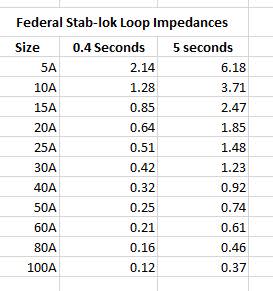
For anyone looking in future, the following table (apparently) contains the published data for the British-made Federal Electric Stab-Lok breakers - it comes from the internet, so value the data according to the price you're paying for it. [wink]

Federal_Stab-Lok_ELI_values_tc4kbc.jpg
 
jraef said:
"Magnetic" trips are not magnetic


Look at page 31 in Eaton's buy log, it is indeed refereed to as a "magnetic pole piece":


Seen this a number of times across various breaker literature. Could the armature itself not be a magnet? Sure, but the theory of induction and magnetic fields still hold true and that is the force which initates unlatching.


ScottyUK said:
No mag trip? That's a little worrying given the high prospective fault levels we have on many of our boards. sad

Worrying in that an arcing or sputtering fault could sustain itself for some time. At 240 volts nominal, it is possible to sustain an arc, and such a condition has a non linear wave form which only increases the amount of time that strip will heat up to bend back. Ie a 2000 amp peak arc could look like an 80amp sine wave overload to the bi-metal.


The little strip itself isn't magnetised, but it is attracted by a magnet. Conclusion: it's probably a piece of mild steel. I can see how a sufficiently large current might induce some mutual attraction between it and the current-carrying bi-metal, but I can't imagine there being much force involved. If I get time I'll see if we can contrive some sort of test using the primary injection set and see what these actually do.

Most likely. Chances are very large current will induce force, and even if that force acts on the bi-metal in a downward pull, said bi-metal must still heat up first in order to bend back. You could call it magnetically assisted thermal tripping, assuming it makes a big enough difference to start with.


Back in the 1970's when these things were installed, BS 3971 was the prevailing standard for MCB's rather than today's BS EN 60898. BS 3971 defined characteristics as Type 2, Type 3 and Type 4. Presumably there is also a Type 1, although I have never actually seen one. My limited understanding is that the Type 4 curve covered a range which could be as high as 50x depending on the MCB manufacturer.

For anyone looking in future, the following table (apparently) contains the published data for the British-made Federal Electric Stab-Lok breakers - it comes from the internet, so value the data according to the price you're paying for it. wink

Being FPE- who knows. [pipe]
 
The bi-metal element is probably half iron and half something else - copper being the obvious candidate. From what I can observe of the mechanism, the steel strip is fairly rigid, and any magnetic interaction would tend to attract the bi-metal toward the steel strip, releasing the latch. It's tricky to simulate by hand because of the lack of mechanical support for the mechanism when the cover is split. I may drill a little hole so I can insert a pin to gently push the bi-metal toward the strip, just to see if my hypothesis is correct.
 
But- don't forget to compare that to a modern breaker, either US or IEC. What you see will be eye opening when compared.
 
Status
Not open for further replies.

Part and Inventory Search

Sponsor