Stress_Eng
Aerospace
Hi to all you FEA guys! Hoping you can shine some defining light onto an FEA aspect where I need to gain some more clarity.
The subject where I would appreciate your input is the FE analysis of pin loaded lug and clevis joints.
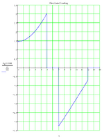
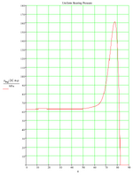
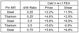
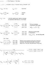
I've challenged myself to the task of creating a hand analysis template that calculates aspects such as the max principal and shear (tresca) stresses, and also the bearing contact loads for a lug. I would like to compare the output of my hand calculations to the results obtained from an FE analysis. This is a personal home project only, and as such I have no test data to compare to. My aim is to gain insight into the contact modelling of such joints, and to know that the approach I'm taking is relatively realistic.
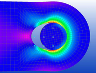
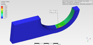
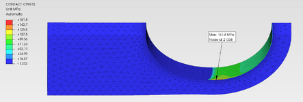
Where I think I need more clarity is in the settings applied to the contact surfaces, in particular the pressure overclosure slope parameter 'k' given as N/mm^3 (surface contact stiffness). I'm using open source software to create the 3D model (FreeCAD) and to conduct the FE analysis (PrePoMax, version 2.2.0). The pictures shown are of the 3D model and the 1/4 FEM (grey lug, green clevis).
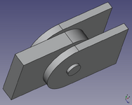
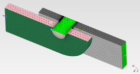
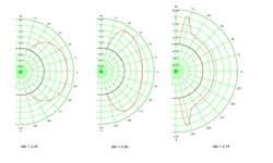
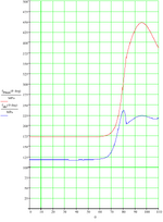
The FE models I've created consist of an Aluminum Alloy Lug and Clevis, with Steel or Titanium Pins. I'm also modelling different sized pins (same lug length). The pin diameter to lug width ratios are 0.25 (as shown), 0.50 and 0.75. PrePoMax uses the Calculix solver, and the 'k' values are based on the modulus factored by a value between 5 and 50. For the combination of materials, I'm using the analysis approach given in Roark, for two dissimilar materials in contact, to obtain a base-line modulus value. Some say to use a 'Hard' setting, although the 'k' value of which I don't know. Others say that a hard setting is too high and a lower value based on E should be used. In addition, some say that the 'k' value should be a function of E and thickness. I've tried a few variations. The max principal stress doen't seem to be too sensitive to the 'k' value, but the Tresca stress does vary somewhat.
Any input you can give would be much appreciated.
The subject where I would appreciate your input is the FE analysis of pin loaded lug and clevis joints.
I've challenged myself to the task of creating a hand analysis template that calculates aspects such as the max principal and shear (tresca) stresses, and also the bearing contact loads for a lug. I would like to compare the output of my hand calculations to the results obtained from an FE analysis. This is a personal home project only, and as such I have no test data to compare to. My aim is to gain insight into the contact modelling of such joints, and to know that the approach I'm taking is relatively realistic.
Where I think I need more clarity is in the settings applied to the contact surfaces, in particular the pressure overclosure slope parameter 'k' given as N/mm^3 (surface contact stiffness). I'm using open source software to create the 3D model (FreeCAD) and to conduct the FE analysis (PrePoMax, version 2.2.0). The pictures shown are of the 3D model and the 1/4 FEM (grey lug, green clevis).


The FE models I've created consist of an Aluminum Alloy Lug and Clevis, with Steel or Titanium Pins. I'm also modelling different sized pins (same lug length). The pin diameter to lug width ratios are 0.25 (as shown), 0.50 and 0.75. PrePoMax uses the Calculix solver, and the 'k' values are based on the modulus factored by a value between 5 and 50. For the combination of materials, I'm using the analysis approach given in Roark, for two dissimilar materials in contact, to obtain a base-line modulus value. Some say to use a 'Hard' setting, although the 'k' value of which I don't know. Others say that a hard setting is too high and a lower value based on E should be used. In addition, some say that the 'k' value should be a function of E and thickness. I've tried a few variations. The max principal stress doen't seem to be too sensitive to the 'k' value, but the Tresca stress does vary somewhat.
Any input you can give would be much appreciated.

