Continue to Site

Eng-Tips is the largest engineering community on the Internet

Intelligent Work Forums for Engineering Professionals

  • Congratulations IFRs on being selected by the Eng-Tips community for having the most helpful posts in the forums last week. Way to Go!

Femap : Revolve Parabolic element

Status
Not open for further replies.

Bcabot

Mechanical
Jan 15, 2013
6
Hi,

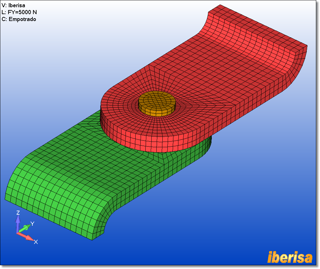
I am trying to revolve parabolic elements on a plane surface in FEMAP 10 but because the elements lies on the axis of revolution it doesn't create the wedge type elements at the axis of rotation. If I revolve linear elements it work fine but i don't get a smooth round revolve that i would get with midside node

Any idea?
 
Replies continue below

Recommended for you

You will probably get a faster, and almost certainly a more usable, response if you were to post Femap questions in the 'Siemens: Femap' forum:


John R. Baker, P.E.
Product 'Evangelist'
Product Engineering Software
Siemens PLM Software Inc.
Industry Sector
Cypress, CA
Siemens PLM:
UG/NX Museum:

To an Engineer, the glass is twice as big as it needs to be.
 
Hi,

here are 2 picture

1st one is the 2D surface with mesh using midside nodes and the 2nd one is after the revolve showing the error.

thanks
 
Hello!,
You have two options here:
1.- Revolve 2-D linear elements using "Mesh > Revolve > Element" command, and then convert to high order using "Modify > Update Elements > Linear/Parabolic order", or
2.- A better meshing approach is instead revolving elements around Z-axis, why not create a quality 2-D mesh of the circle based in QUAD elements, and then to extrude the 2-D mesh to create a perfect 3-D HEX mesh avoiding triangular wedge elements?. Also, this way your 2-D mesh could be parabolic, so not any limitation exist -- enjoy!.

chexa_malla_3d.png


Best regards,
Blas.

~~~~~~~~~~~~~~~~~~~~~~
Blas Molero Hidalgo
Ingeniero Industrial
Director

IBERISA
48011 BILBAO (SPAIN)
WEB: Blog de FEMAP & NX Nastran:
 
Hi,

Thank you for your comments. Unfortunatly it doesn't fix my problem.

suggestion 1) if you revolve with the linear element the revolve is not curve but has straight line between the nodes. []
getfile.aspx


what i am looking for ir more like the blue line here []
getfile.aspx


Sugestion 2) Unfortunalty the picture i sent posted were just a basic model for a more complex model witch the extrude feature would not work, here is a picture of the model
getfile.aspx


Any other suggestion?

Ben
 
Dear Ben,
Revolving 2-D mesh using low-order plot planar elements is perfectly valid, the KEY here is to have geometry associated to the mesh, then FEMAP will ask you "OK to Move Midside Nodes to Geometry?". Please do the following steps:
1.- Revolve the 2-D mesh low-order, as explained.

hexmeshingiii_3dmesh_rotate.png


2.- Revolve the base surface as well (the one you mesh to create the 2-D plot planar mesh) to create a 3-D solid using "Geometry > Solid > Revolve".

3.- Associate the 3-D solid mesh to the solid body created in the previous step using "Modify > Associativity > Automatic". Now the mesh is fully associated with the geometry, then the solid mesh with solids is associated with surfaces, you can apply loads & BCs to the geometry (surfaces) diectly and be transfered to elements & nodes.

4.- And finally convert the linear to parabolid mesh using "Modify > Update Elements > Linear/Parabolic order". FEMAP will detect that the 3-D solid mesh is associated to geometry, then the command will ask you to mode midside nodes to the gometry, here you are the result:

chexa_midside_nodes.png


Best regards,
Blas.

~~~~~~~~~~~~~~~~~~~~~~
Blas Molero Hidalgo
Ingeniero Industrial
Director

IBERISA
48011 BILBAO (SPAIN)
WEB: Blog de FEMAP & NX Nastran:
 
Hi,

after working with the sugested method, I find that the midside node created this way create 2 straight line between the corner nodes and not a curve.

is there a way to get a curve (arc) ?

Thanks

Ben
 
Dear Ben,
Plot both the geometry base, nodes & elements, and make sure that midside nodes are located in the curved edge, not in the straight line between the corner nodes. Make sure you run FEMAP V10.3.1B or newer version V11.0, if you run an older version of FEMAP then the above procedure could not be efective.
Best regards,
Blas.

~~~~~~~~~~~~~~~~~~~~~~
Blas Molero Hidalgo
Ingeniero Industrial
Director

IBERISA
48011 BILBAO (SPAIN)
WEB: Blog de FEMAP & NX Nastran:
 
Status
Not open for further replies.

Part and Inventory Search

Sponsor