Hi... Everyone, I need to implement a n point fft on a Fpga. So, for the testing purpose I have created a simulation model to test the output of the n point fft and ifft model. The output from the n-point FFT HDL Optimized block is different from FFT block output. Whats going wrong with this simulation? How do I need to modify the model?
Simulink model
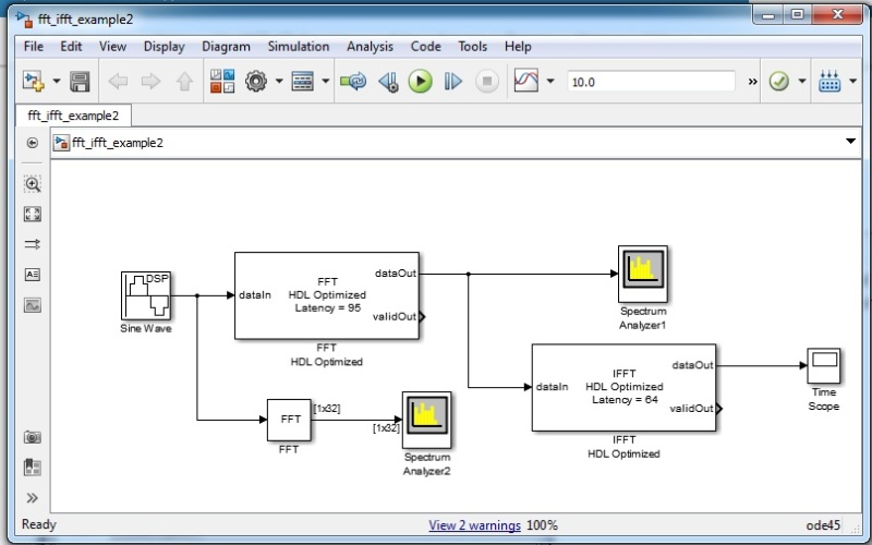
Configuration is as follows.
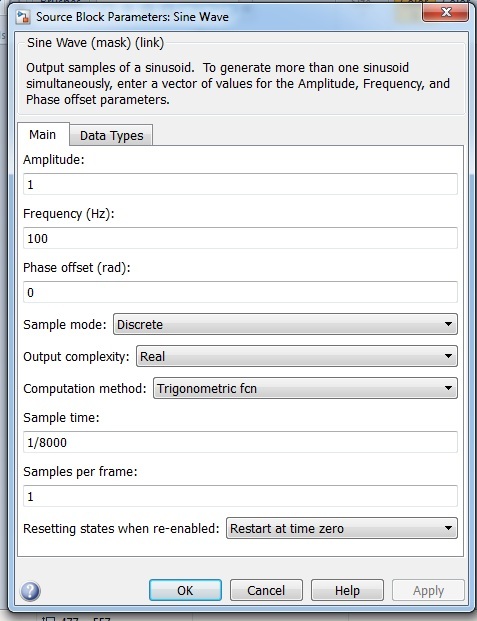
1. Created a sine wave with following parameters.
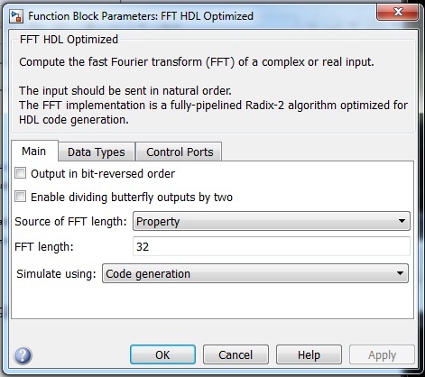
2. Parameters of FFT HDL Optimized block
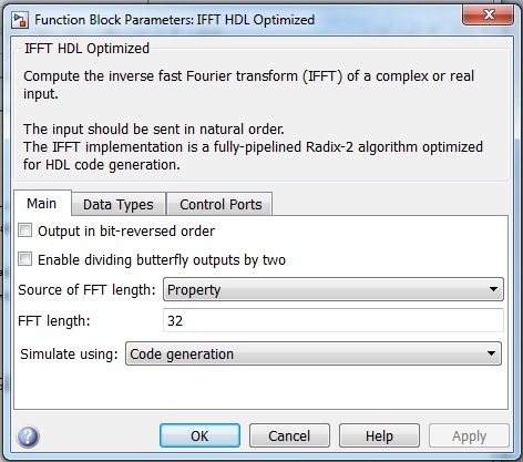
3. Parameters of IFFT HDL Optimized block
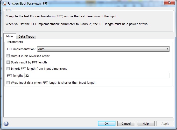
4. Parameters of FFT block
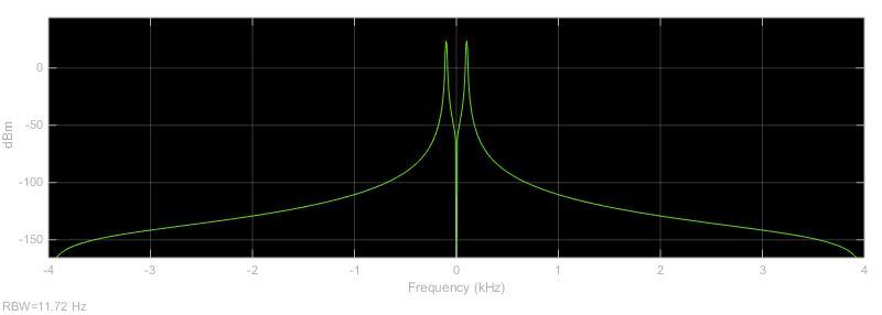
5. Figure of FFT HDL Optimized block output
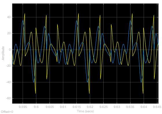
6. Figure of IFFT HDL Optimized block output
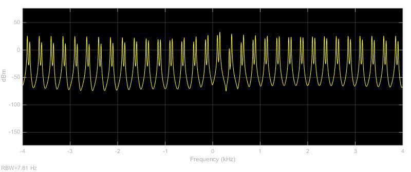
7. Figure of FFT block output
Above (Figure of FFT block output) is the desired output. But fft/ifft hdl optimized outputs gives a wrong result. Please help me on this problem.
Thank You!
Simulink model
Configuration is as follows.
1. Created a sine wave with following parameters.
2. Parameters of FFT HDL Optimized block
3. Parameters of IFFT HDL Optimized block
4. Parameters of FFT block
5. Figure of FFT HDL Optimized block output
6. Figure of IFFT HDL Optimized block output
7. Figure of FFT block output
Above (Figure of FFT block output) is the desired output. But fft/ifft hdl optimized outputs gives a wrong result. Please help me on this problem.
Thank You!