Continue to Site

Eng-Tips is the largest engineering community on the Internet

Intelligent Work Forums for Engineering Professionals

  • Congratulations waross on being selected by the Eng-Tips community for having the most helpful posts in the forums last week. Way to Go!

Fig 7-39/2018 question

greenimi

Mechanical
Nov 30, 2011
2,316
7-39 - Copy.jpg

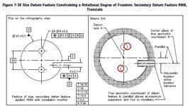
In fig 7-39/ ASME Y14.5-2018

I think we all agree that the two bores should be “squiggly” (in the same way the outside diameter is shown a little “bumpy”), but my question is:
Do you think the correct way is to show the two (“squiggly” to be) holes slightly rotated clockwise? (my red adjustements)

I am comparing 7-38 with 7-39 and I am wondering why the holes in 7-39 are not rotated? Should they be? Shouldn’t they be?
Fig 7-38 looks okay, but if the intent is to show the same part on both scenarios (with and without the translation modifier) then why 7-39 does not show rotated holes?
 
Replies continue below

Recommended for you

Hi Greenimi,

Can you also share Fig. 7-38? I don't own a copy of the spec.

Then if you own (and I expect as a trainer you do) 2009 version of the ASME Y14.5 then figure 4-32 is the one you want to reference.
 
They are showing the rotation of the datum feature . The features referring to won't rotate.
 
They are showing the rotation of the datum feature . The features referring to won't rotate.
Why not rotate? Isn't it the same part as in fig 7-38?
I think it is the same intent......
 
Then if you own (and I expect as a trainer you do) 2009 version of the ASME Y14.5 then figure 4-32 is the one you want to reference.
Sorry, I do not. When I was directly employed the company had a copy. I never bought one for myself. I am not a GD&T trainer, just an experienced user. Are the older versions available for free download (legally)?
 
Why not rotate? Isn't it the same part as in fig 7-38?
I think it is the same intent......
It is not the same part. It is showing that the datum features are different for the same result.
 
greenimi,
Had 7-39 been showing the holes rotated that would suggest the translation modifier provides some kind of additional leeway for the holes (like datum shift), but that is not the case.
 
It is not the same part. It is showing that the datum features are different for the same result.
So what that does mean? That the datum reference frame does not matter? Therefore, regardless of the datum features you can get the same result?
 
Same type of comparison made in Fig. 7-36 vs. Fig. 7-37 and so on. The features don't move, the datum features do.
 
The datum features are limited by the tolerances qualifying them and don't "move". The datum feature simulator for the clocking datum feature is allowed translation and is unfixed from its basic location relative to the primary datum A axis, to allow better engagement with the actual, as-produced datum feature B.
 
The datum features are limited by the tolerances qualifying them and don't "move". The datum feature simulator for the clocking datum feature is allowed translation and is unfixed from its basic location relative to the primary datum A axis, to allow better engagement with the actual, as-produced datum feature B.
Well, in fig 7-39 we are NOT talking abot clocking. We are talking about aligning.
So I would say that orientation determines the alignment of the remaining axes of the datum reference frame.

I think clocking is applied when no translation modifier is used (fig 7-38).
 
The datum features are limited by the tolerances qualifying them and don't "move". The datum feature simulator for the clocking datum feature is allowed translation and is unfixed from its basic location relative to the primary datum A axis, to allow better engagement with the actual, as-produced datum feature B.
So, I am saying that the physical reality of the part in fig 7-39 will make the 2 holes (the patten) to rotate slightly, clockwise.
 
Well, in fig 7-39 we are NOT talking abot clocking. We are talking about aligning.
So I would say that orientation determines the alignment of the remaining axes of the datum reference frame.

I think clocking is applied when no translation modifier is used (fig 7-38).
I disagree, 7-39 IS about clocking too. Will explain later if no one else will before me. Stay tuned.
 

Part and Inventory Search

Sponsor