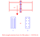
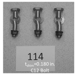
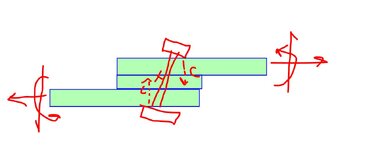
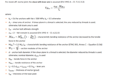
For finger shims used in the erection of steelwork, often these have slots to allow them to either be installed horizontally or vertically as required. For the case of an endplate splice or some variant of a plate to plate connection, you may have the scenario when you have a slotted shim separating the endplates, with slots orientated in the direction of the shear force as shown below. For standard filler plates, codes generally have some form of bolt strength reduction factor similar to the equation shown below (taken from Australian standard) which is based on the thickness of the filler plate. Would anyone know if this equation is still valid in the case that the shims are slotted? I..e is this a generic "gap between plates" strength reduction equation, or specifically for the scenario in which you have a "full" filler plate as in fig 2 below. I can find no reference to this in codes or design guides, yet these kind of slotted shims seems to be common practice in steel erection. My thinking is that for the full filler plate (2 in image below) if any bending of the bolt occurs due to the presence of the filler plate, there is some kind of clamping or jamming action occurring which may be captured in the bolt strength reduction equation (which from my understanding are generally empirically based) whereas with the slotted shim this would not occur and you'd get more of a pure bending of the bolt, and hence less capacity.


