Continue to Site

Eng-Tips is the largest engineering community on the Internet

Intelligent Work Forums for Engineering Professionals

  • Congratulations IDS on being selected by the Eng-Tips community for having the most helpful posts in the forums last week. Way to Go!

Fillet problem on simple part 1

Status
Not open for further replies.

CNSZU

Mechanical
Sep 2, 2005
318
Hi everyone,

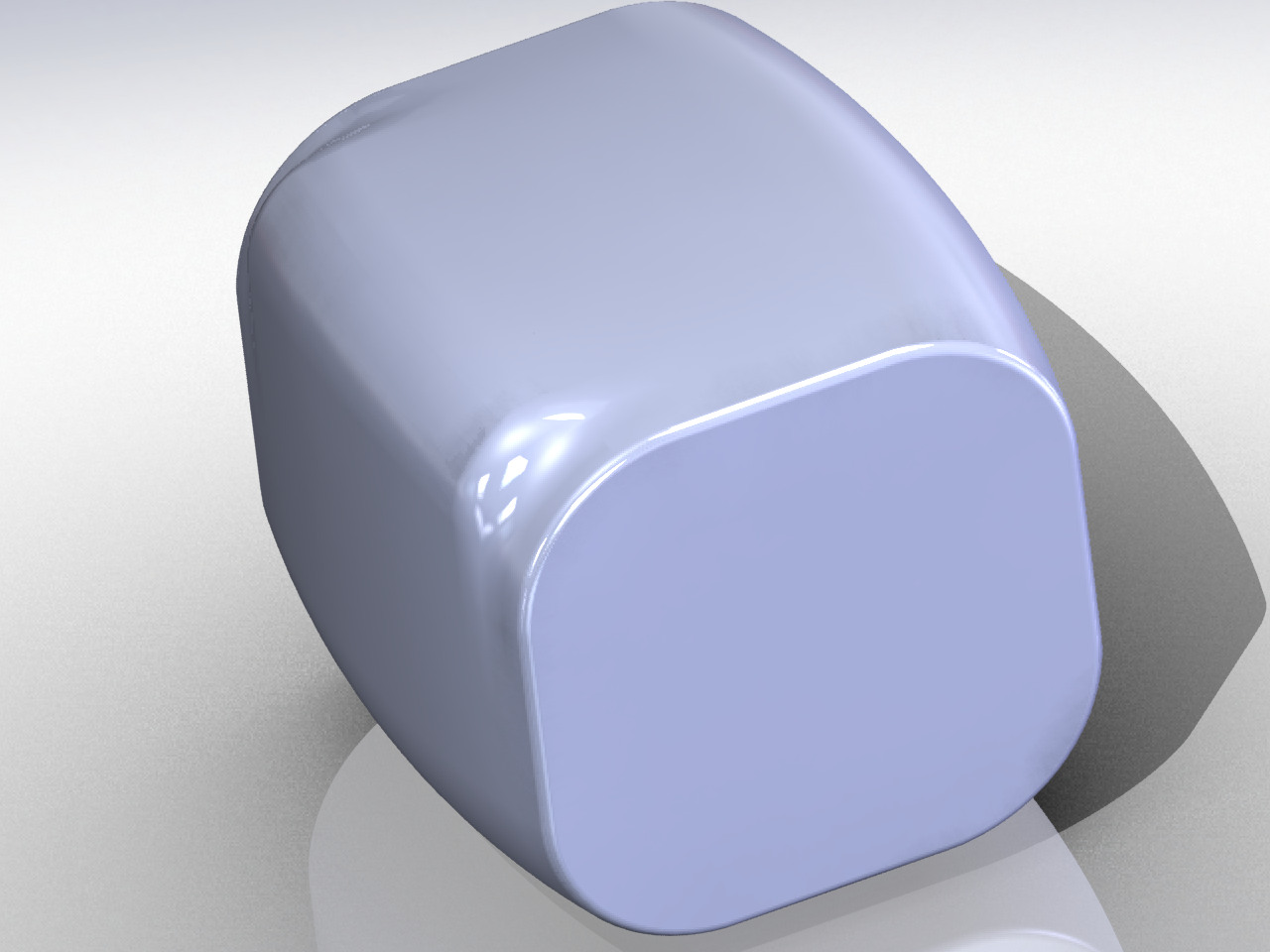
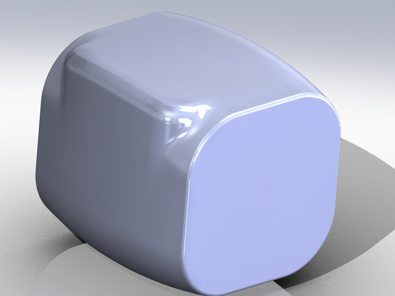
I finally managed to create this part more or less how I want it using surface techniques, because it's impossible building the exact same part with solids. Even then, the allowed range of fillet size is very limited, and will easily fail to create fillets. Why is this part so difficult? Is solidworks not suitable to create this kind of part? Should I use a surfacing tool, like Alias or Rhino instead?

 
Replies continue below

Recommended for you

Complex fillets are definitely not SW's strong point.

Can you post the part to play with?
 
Sure, here are 3 solidworks 2011 files - each modeled differently, but none are perfect.

The RAR file contains:

solid - fillet fail.SLDPRT (fillets can't be added)
half solid half surf - fillet fail.SLDPRT (fillets can't be added)
surface - almost ok.SLDPRT (constructed entirely with surfaces, very complicated, but fillets can be added, although not very reliably)

I challenge anyone to build this part using mostly simple solid techniques and add the fillets.

If that fails, I would like suggestions on which CAD program can reliably create this part.

What baffles me is that this part is not complicated at all, just a swept, rounded box and a protrusion. It should be a piece of cake to put these fillets in, yet I've spent many hours on ripping my hair out over this.

 
 http://files.engineering.com/getfile.aspx?folder=26e6ae60-bdfa-4dae-bd55-af15b73d9bcb&file=solidworks_-_fillet_problem.rar
What baffles me is that this part is not complicated at all, just a swept, rounded box and a protrusion. It should be a piece of cake to put these fillets in, yet I've spent many hours on ripping my hair out over this.
The part is very complicated mathematically. It just looks simple.

So here you go:
Version 1
ABomb.png


Version 2
ABomb2.png


TOP
CSWP, BSSE
Phenom IIx6 1100T = 8GB = FX1400 = XP64SP2 = SW2009SP3
"Node news is good news."
 
kellnerp, could you post the solidworks files (sw2011) of the 2 versions? I would like to see how you've modeled them, or repost the images with tangent lines showing.

In the meantime, I've looked more deeply into this problem and found a solution.

First, I used the Geometry Analysis tool to find knife vertices. Some are good, and some are bad. The bad knife vertices need to be eliminated. I figure the problem with the bad knife vertice is that the main body surface and protrusion surfaces share a large area. So I decided to make the protrusion start at exactly the point where the surfaces separate. To find this point, I used the original sketch for the main body, at the sketch fillet. Then I used the Geometry Analysis tool again to confirm that I got rid of the knife vertice. Now I can add fillets in any size without problems.

Here are images with explanations:


Wow, thanks kellnerp! I'm particularly impressed by the "atomic bomb fillet" and "delete and fill face" techniques which I was unaware of.

An additional question, in the FAQ file "face blend shells, regular does not.SLDPRT", there was an alternative to using face fillet, by using delete and fill face - how do you know which face should be deleted and filled? Do you have to try it for every single face in the part to find out which are the offending faces?
 
Status
Not open for further replies.

Part and Inventory Search

Sponsor