I work on both solid laminate and cored panels and when I am running sol105 buckling runs, I will get hundreds to thousands of the short choppy crimping modes that are a result of low G13,G23 stiffness of the foam core with real modes interspersed throughout. I typically look for at least 4 nodes per 1/2 sinewave for it to be real vs choppy modes and by choppy I mean where each adjacent node is the max/min peak of the sinewave. Clicking through each mode is very laborious.
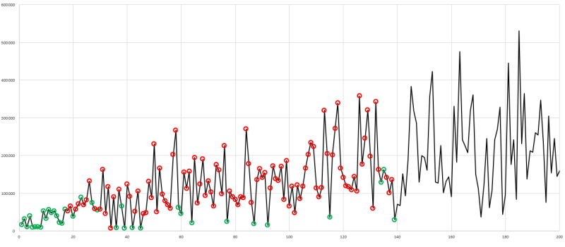
I had the idea of using total strain energy output to f06 to see if there was a pattern to which real modes vs crimpy modes could be filtered. This worked reasonably well but not well enough (pic included which shows the first 200 modes on x axis, y is total strain energy, red circles are crimping modes, green are real modes). real modes typically appear with low strain energy, however this is not a bullet proof method. I had the idea to output the max nodal magnitude rotations for the top 10 nodes per mode. My thinking is the short crimpy modes should have very very high nodal rotations as each adjacent node will be the peak and minimum of the sinewave. Whereas with a real buckling mode, there should be smooth waves with reasonably small nodal rotations.
My problem is I can only get MaxMin to output to the .f06 for the static case of the 105 solution, not for each mode. These are the two lines I added to the Global Requests and conditions start text (case control) in FEMAP.
"ESE(PRINT, THREASH=100.) = ALL" <--- this works and outputs total element strain energy for each mode
"MAXMIN(VMAG=10,CID=0,DISP)=ALL" <-- I can only get this to outputs for the static
Anyone know why I can't get MAXMIN() to output displacements for each mode? ORRRR have a different way to solve my overall problem of finding the real modes easy and efficiently
note: I am covering the crimping modes with hand calcs.