Continue to Site

Eng-Tips is the largest engineering community on the Internet

Intelligent Work Forums for Engineering Professionals

  • Congratulations KootK on being selected by the Eng-Tips community for having the most helpful posts in the forums last week. Way to Go!

Filtering data from impact hammer test

Status
Not open for further replies.

E2015

Civil/Environmental
Apr 20, 2015
22
Dear all,

I have acquired some data by using instrumented hammer and 8 accelerometers.
The data has been acquired on a railway track on a timber sleeper.
Now, I want to analyse the data in the frequency domain.
Usually I am interested in the lower frequency range up to 1000Hz.

When I calculated the corresponding FRFs for every accelerometer some of them are very noisy (channel 6,7, and 8). Channel 6,7 and 8 are the furthest from the impact location.
The rest of the channels (1,2,3,4,5) have more cleaner FRF curves with visible peaks.

I also tried to filter out the data, but I think I got lost in this part since I don't understand how the filtering is applied.

Basically I need few tips how to start getting more cleaner FRFs. So, my questions are following:

1. How to decide in general which digital filter should be applied? Is there a rule for this?

2. Is it recommended to always filter out the data? Can other info from the signal be lost?

3. What is the best filter I should apply in order to get more clean FRFs for my application?

Many thanks in advance!

Emina B.
 
Replies continue below

Recommended for you

I realise your data is top secret but don't you think it would be easier for us if you could post an example or two?

Anyway, filtering hammer data is tricky. I'm hoping you still have the raw data, as your only hope is time domain filtering.

The usual problem with the force channel is too much noise after the impact has decayed. I like to use pretrigger and a rectangular window.

Filtering the accelerometer channels in the time domain is a bit trickier as they usually ring for a lot longer (remember to apply the same pretrigger to them). I've had some success cleaning up a channel with exponential windowing, but if the data ain't there, it ain't there. What do your coherence plots look like?

Incidentally if the data is anything like clean then I prefer not to use windows, at least as a check, so I can see what artefacts the windows have introduced.

Once you have FFTed the transfer functions and averaged them (how many averages did you use?) then there is not much you can do.

This forum has an FAQ with some links to signal processing on line resources.


Cheers

Greg Locock


New here? Try reading these, they might help FAQ731-376
 
Digital filtering is usually not applied on impact test data. I second Greg's suggestion of looking at the coherence and windows used. If your measured raw time signal amplitude is about the same amplitude when no excitation is present (noise floor), there is not much one could do with the existing data.

If you are in the position of performing more tests, try accelerometers with higher sensitivities and try multiple impact locations. This would help you check reciprocity and help the curve fitter.


Good luck,
Sze Kwan (Jason) Cheah
 
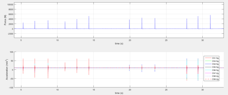
I have attached data I acquired for one sleeper in time. Both force and acceleration are presented.
Force_Acceleration_All_impacts_hhkd7f.png

Fig 1. Force and Acceleration for all impacts and all channels
Force_Acc_zoom_fkqvqe.png

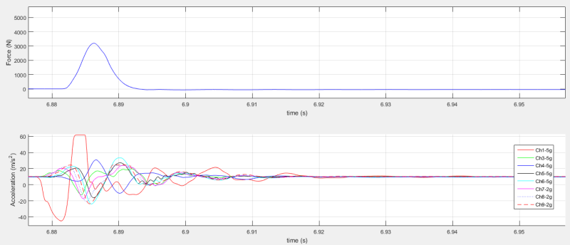
Fig 2. Force and acceleration for impact at sleeper right end side
Force_Acc_hn1pc7.png

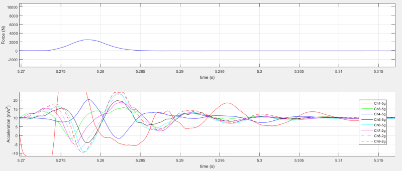
Fig 3. Force and accleration for impact at sleeper right end side-zoomed in
Accelerance_Functions_rffayp.png

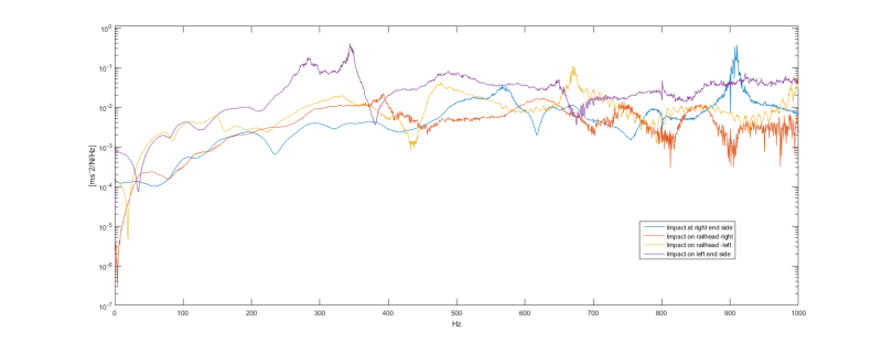
Fig 4. Accelerance functions for channel 1 for impact at sleepers end on the right hand side; top of railhead on the right side, top of railhead on the left side; and sleepers end on the left hand side . Channel 1 is located on the end of the sleeper on the right end side.
accelerances_for_all_channels_for_impact_at_right_end_side_vkoexq.png

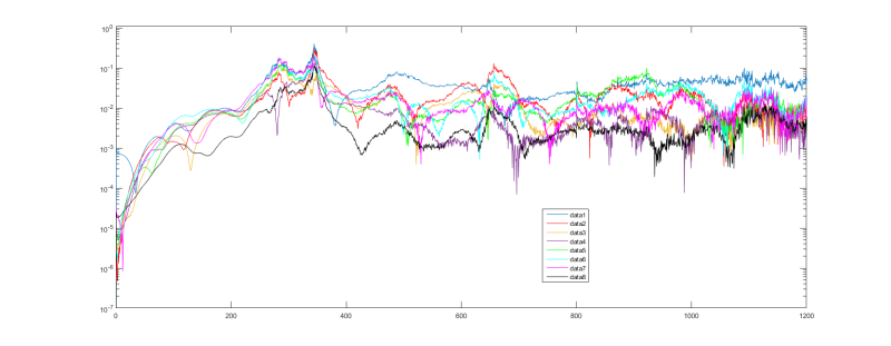
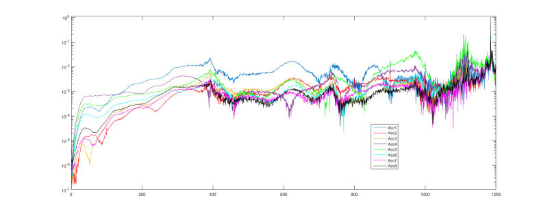
Fig 5. Accelerances for all channels when the impact is done on sleepers end at right hand side.
accelerances_for_all_channels_for_impact_at_left_end_side_kf3awo.png

Fig 6. Accelerances for all channels when the impact is done on sleepers end on the left hand side.
accelerances_for_all_channels_for_impact_at_railhead_at_left_end_side_xuxlwu.png

Fig 7. Accelerances for all channels when the impact is done on topf of railhead on the left hand side.
accelerances_for_all_channels_for_impact_at_railhead_at_right_end_side_fhgb7v.png

Fig 8. Accelerances for all channels when the impact is done on topf of railhead on the right hand side.


I have used +/-2g and +/-5g range MEMS DC accelerometers. Sensitivity for 5g acc was within 394 to 411 mV/g, whereas the sensitivity of 5g acc was within 998 to 1016 mV/g.

The impact hammer is PCB 086D50 with 5,5kg and soft tip.

The 2g acc were overranged when the impact location was in their vicinity. The impacts were done at both sleepers end and on top of the rail head at both rail seats. So in total I had 4 groups of impacts and within every group 3 hammer impacts are done.

I will be able to do more testing, but first I want to have a plan how to post-process the data and the future one I get.

Thank you,

Emina
 
Hi Emina,

As a casual observer, my guess is the soft tip provides excitation at only the low frequencies (<300Hz?). That may explain why the response higher frequencies are 'noisier' compared to the lower frequencies for all channels. This is effectively a physical low pass filter. A way to confirm this is to plot the autopower spectrum of the hammer. If the above is true, try switching to a harder tip.


Good luck,
Sze Kwan (Jason) Cheah
 
You need to compute Coherence Function, if you have not done it yet to check data quality. What color hammer tip did you use? A soft tip like the Gray color is only good for about 200-Hz F-max or less. What modes/frequencies are you interested in? Are you triggering measurements on Force. If yes, then you should only have one impact per time window. MEMS accelerometers do not have wide dynamic range as conventional ICP/IEPE piezoelectric accelerometers.

Walt
 
If I can read your timescale correctly the pulse for the force is about 0.01 seconds long, so the cutoff for the force input will be 100 Hz or so. Other than that the results don't look too bad.

I'd always include the phase plots and coherence

Also try checking the reciprocity, and try the effect of different force levels.

Cheers

Greg Locock


New here? Try reading these, they might help FAQ731-376
 
"the cutoff for the force input will be 100 Hz or so"
The accelerations are plotted to 1200 Hz, and OP said a "soft" hammer tip was used. How "good" is the data above 100 Hz, without seeing Coherence plots?

Walt
 

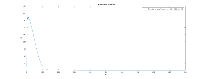
This is the autopower spectrum of the force for impact on top of the sleeper
Autopoer_of_force_ymrnjl.png


I have used a soft tip, brown color. Also my interest now is for frequencies under 1000Hz.
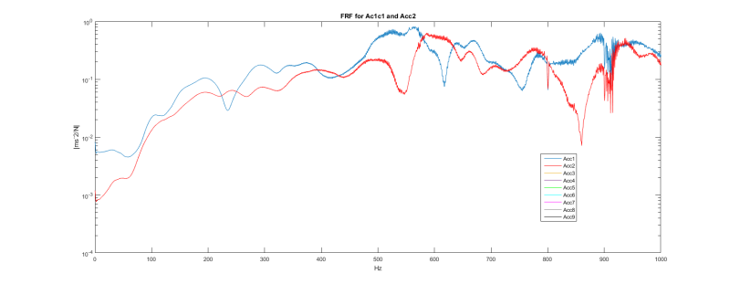
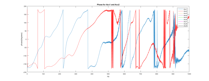
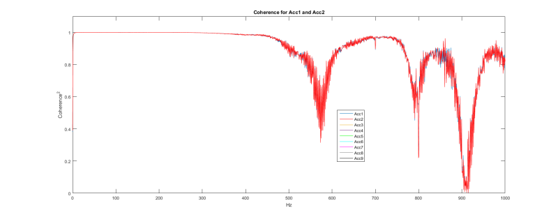
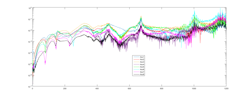
The following figures show FRF, pahse and coherence for two accelerometers and impact on on top of the sleeper. Also, I have plotted coherence^2 for these.
FRF_Detrended_Data_UnfAc1Ac2_kzxpcg.png


PhaseUNiflteredAc1Ac2_lcfxhm.png


CoherenceAc1Ac2_xwh7s6.png


I am not so sure can I get anything from this data. I was expecting to be able to obtain first five mode shapes and corresponding natural frequencies. I haven't used triggering throughout the testing. The data acquisition software was SignalExpress from NI.

I don't quite understand what you mean with reciprocity (of what?).

I haven't applied any filters on the force or acceleration data. I applied detrend (by subtracting the mean) to acceleration data to remove the gravity effect. The FRfs I have calculated as cross spectrum
between the force and acceleration, divided by the autospectrum of the force. I used for this cpsd function in Matlab with Pwelch spectra estimate; rectangular window with 50% overlapping;window length = NFFT/4.

Do you think I can proceed further with data analysis, e.g. filtering out the frequencies of interest?
Is there anything else I could do with the data in time domain?

Thanks,

Emina


Emina B.
 
According to the Force spectrum, there is no force input into the structure above 100 Hz. Why would the Coherence be so high and flat to 400-Hz and near 700-Hz? Reciprocity means that the same TF result should occur if you exchange the impact and response locations. Frankly, I would improve the test procedure on an easier structure and use only one accelerometer to get some confidence.

Walt
 
So the response spectrum shows very little energy above 110 Hz and virtually none above 250. You need that line to be flattish over the frequency range of interest. I'd switch to a harder tip.

Cheers

Greg Locock


New here? Try reading these, they might help FAQ731-376
 
Hi Emina,

OP said:
This is the autopower spectrum
The auto-power is traditionally shown in the log-y axis similar to transfer function. Maybe that would show it trending down sharply after 300Hz. Do you get something similar to Blue line of Figure 1 of [URL unfurl="true"]https://www.uml.edu/docs/oct98_tcm18-189815.pdf[/url]? Please compute it as described below.

OP said:
I haven't used triggering throughout the testing
Please see: [URL unfurl="true"]https://www.uml.edu/docs/aug01_tcm18-189833.pdf[/url]
Each impact of the hammer produces vibration that decays within it's own time block. You have 12 hits so there are 12 averages of those blocks. The data in between the time blocks are mostly noise and thus discarded.

OP said:
I don't quite understand what you mean with reciprocity (of what?)
Reciprocity is very useful. Here's a good write-up on it: [URL unfurl="true"]https://www.uml.edu/docs/Dec08_tcm18-189884.pdf[/url].


From your description, am I right to guess you're acquiring the time signal with NI/Signal Express and post processing the data in MATLAB with your own code? If so, I agree with [bold]Strong's[/bold] recommendation on first verifying your code with known structure to get known results.

A suggestion for next step is to extract the right time block with pre-triger and block length containing enough data samples such that the signal decays completely within the block. Rectangle window can thus be used. Each corresponding impact hammer signal block should have the same time stamp. Compute the transfer function and coherence for each accelerometer channel. Avoid digital filters.

I'm not familiar with Welch's PSD. I usually just use the [tt]fft[/tt] function straight up to compute the cross & auto-powers.

p/s: I'm a fan of Pete's concise style of describing modal concepts. Here's more:
[URL unfurl="true"]https://www.uml.edu/Research/SDASL/Education/Modal-Space.aspx[/url]
[URL unfurl="true"]https://www.uml.edu/docs/Young_Engineer_IMAC21_2003_assembled_MACL_tcm18-189941.pdf[/url]


Good luck,
Sze Kwan (Jason) Cheah
 
Status
Not open for further replies.

Part and Inventory Search

Sponsor