Continue to Site

Eng-Tips is the largest engineering community on the Internet

Intelligent Work Forums for Engineering Professionals

  • Congratulations IDS on being selected by the Eng-Tips community for having the most helpful posts in the forums last week. Way to Go!

Flag Pole Foundation - calculations vs typical 2

Status
Not open for further replies.

beamertaylorf

Mechanical
Sep 17, 2020
16
I'm a Mechanical engineer but I was asked to look into this for a friend. So far, I've been unable to make any sense of it! I've looked around this forum a lot and haven't found a post directly aimed at this weird ground set foundation sizing.

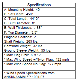
The scenario is for a 40 ft flag pole that seems to be non-constrained at grade. The wind load on the pole and flag totals about 12,000 ft-lb from how I have understood NAAMM FP 1001. The manufacturer has told my friend that this design works and has worked, but I haven't been able to get anywhere close to this small of a foundation in my calculations. I even had a Civil friend of mine run this through EnerCalc and that wasn't able to get close either. My own Excel based calculations are coming up with about 10 ft of embedment depth required for a 24 in diameter ground set.

Does anyone have any experience with these kinds of "ground set" foundations? It seems that there are "typical" dimensions out there from an old NAAMM publication that I can't find; it seems to be retired. Any experiences or thoughts on this would be a great help to my construction manager friend!

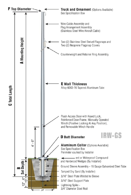
Pole (see attached):
40 ft tall (above grade) flag pole
8 ft x 12 ft flag (max)
4 ft embedment in concrete "ground set" (tapered "plug"/drilled pier)

Foundation/Ground Set (see attached):
Top diameter: 24 in
Depth: 4 ft

Loads per NAAMM FP 1001:
122 mph max wind speed (per given specs)
Axial Load: ~350 lb (weight)
Moment: ~12,000 ft-lb
2_drhkuk.png
1_bkwiih.png
 
Replies continue below

Recommended for you

A 40' flag pole with a 4' deep foundation? Unless that footing is 15' across, I'd say that's laughable. 2' diameter x 10' sounds a little more realistic.
 
10 feet seems in range for what I would expect. Is there an idea of soil type? In a dense gravel type application maybe this has "worked". In a clay soil application, definitely not, or if it hasn't fallen over, there's no way it's still plumb.
 
I think both of you are exactly right. The only other thing I thought of was that my moment calculations were too high, but I've picked them apart and I think they're pretty good - albeit slightly conservative.

In my digging, I found this "typical installation" chart that many manufacturers have online. They aren't all exactly the same but they're close. It seems to be based on the NAAMM Metal Flagpole manual for "good soil conditions".

This specific scenario is for a job in Temple, TX. The soil isn't as bad as where I am around Houston, but it's definitely not heavy gravel or anything of that sort at just 4 feet deep. Even with a 4 ft diameter (larger than the chart below!), I still get an embedment depth of at least 6.5 ft for a 40 ft flag pole.

My construction manager friend has told me that some jurisdictions are requiring a PE stamp for this specification where others have not. Technically, since it is in fact a specification I think it should be PE stamped, which means that it would have to be engineered or re-engineered.


3_huivgl.png
 

Dear beamertaylorf ,

I have an old book , ( Old but Gold, Foundations of Structures by Clarence DUNHAM ,1947 ) which has a section for pole foundations and a nomograph to determine embedment depth..

If you know the soil conditions, you may check the embedment depth.

I have attached the relevant pages of the book..there is a worked example for the nomograph

 
 https://files.engineering.com/getfile.aspx?folder=773beeea-d1c2-4218-b4de-0826f8d61d89&file=phalefundament_mast_(1).pdf
Based on your chart there, it would be two feet wider at the top and the base than what they're suggesting, that's a substantial amount of additional weight to help resist overturning. I still feel the 48" of embedment seems light, but if it was essentially a 4 foot cube (or cylinder) as opposed to 2ft by 4 foot, I'd have warmer feelings towards it.
 
Thank you for taking the time to find that HTURKAK. I've seen this somewhere recently but I'm not sure how to use it. I'll have to see what I can come up with!
 
jayrod12 - for simplicity's sake I was told they drill it as a straight shaft, so that helps a little. I'm not sure they'd want to go through the extra trouble of a square/cube shape if they could just drill a larger and/or deeper hole. But it's not always about what they want, either [wink]
 
I would recommend using the isolated pole factor while doing the pole foundation design, this will help. I would expect if you wanted 4' deep you would be looking at around 5'+ diameter based on previous experiences. I wonder if the manufacturer was using "restrained" and "isolated pole factor" together which is a no-no that I have seen done way too many times, especially for flag poles and parking canopies.
 
I agree with that. I was more pointing out the discrepancy on diameter. I love the "We've used this before and it worked" argument when it's not the same installation.
 
Aesur - thanks for pointing that out. I missed that in my review of 1806 and 1807. It does help a lot. I think my excel calculations for non-constrained are a little off. I had a hard time breaking down my P and M to fit the non-constrained equation, but the constrained equation seems ok.

jayrod12 - yeah I see what you mean. I wonder if they've ever had to get a PE stamp before for this... you'd think they would have by now
 
Thanks for confirming my thought process on backing out the force from the moment. I just wasn’t sure, since the non constrained equation uses P and H and the constrained let’s you use M instead.
 
Spreadsheet POLEFDN.xls by Alex T is attached. It has quite a few different methods, including 2012 IBC unconstrained condition.

Also make sure you've got the correct factors on your wind forces (ultimate vs. ASD forces). Considering the NAAMM doc is from 2007 you won't have to convert to ASD forces. (some/lots of people call ASD forces/stresses "working" forces/stresses). I.e., the wind pressure calculation will spit out ASD forces directly since the windspeeds are based on IBC windspeeds prior to 2012. Soil pressure and stability calculations are almost always done using ASD forces. The POLEFDN.xls deals with ASD forces.

Aesur said:
...back calculate the lateral force, which in this case is 12,000/36 = 333.3 lbs.
For example, 333lbs would be the ASD force. So if you were entering it into Enercalc (and using ASCE 7-10 or later load combos), the force you would enter is 333lb/0.6 = 555lbs since enercalc will then apply a 0.6 factor to get it back down to ASD.

And like others have said, 24" diam x 48" for a 40' flag pole seems quite suspect. 6-10' embedment seems totally reasonable for a 24" diam pier.
 
 https://files.engineering.com/getfile.aspx?folder=38806bc7-edfc-41ca-9544-0d5a11a0926b&file=POLEFDN.xls
I haven’t come across the ASD acronym yet. I’ll be sure to check that out.
 
For what it is worth, the "rule-of-thumb" for embedment depth of distribution utility poles is 10% of the pole length plus 2ft. So, for a 40ft above ground height you would have an overall pole length of 46'-8", with it embedded 6'-8" into the ground (46.67 * 0.1 + 2 = 4.67+2 = 6.67ft).

Now, next time you drive down the road, pay attention to the power poles and count how many are actually still plumb (you probably won't find many).
the 10% plus 2ft generally works for these poles as they don't fall over, but it also generally results in a lot more movement than most typical structures can tolerate and still be considered acceptable.

The one thing that might help is if the flag will be taken down in anticipation of storms, then the chances of the design loading ever happening is pretty slim (A luxury not afforded to the power poles). I should also note, the utility poles don't generally have concrete placed around them, they are usually just backfilled with the excavated soil. Concrete will help with the lateral resistance of the drilled pier foundation.
 
For what it's worth, I live up north where if you don't put the foundation at least 5' deep it won't last more than one season even with little load on it.
Local town put up a new flagpole.
Drilled 36" diameter x 8' deep for a 50' flagpole.
The guy running the job said that 6'6"-7' would be enough but the extra foot was cheap insurance.


= = = = = = = = = = = = = = = = = = = =
P.E. Metallurgy, consulting work welcomed
 
With the EngineersEdge.com calculator that includes the isolated pole factor, and by backing out the P and h values from my total Moment as 333 lbf at 36 ft I get an embedment depth of just over 5 ft for a 24 in diameter foundation.

If I divide the force by 0.6 for a 555 lbf (to cancel out any ASD conversions that may be going on) I get an embedment depth of 6 ft - this is in line with some of the comments above!

The POLEFDN sheet won't let me adjust for the Isolated Pole Factor, but I think it would be in the same range if i could. I tested it by manipulating the Soil drop down to be roughly 2x and it came out to 6 ft too.

Would a 24" x 6' concrete foundation seem fairly reasonable given the discussion that we have had so far? It seems to be in line with several of the opinions set forth in the thread, based on rule of thumb and then calcs using the isolated pole factor. This would at least be fairly close to the original design specs that I listed.
 
I too have attempted to run the numbers on these flagpole setups; and they all fail miserably.

The Civil engineers are always trying to put this detail on one of the structural sheets. I tell them 'heck no' (but I don't say heck).

Usually we end up putting language on the civil sheets to the effect of "light pole per installed manufacturer instructions"
 
Status
Not open for further replies.

Part and Inventory Search

Sponsor