Eng-Tips is the largest engineering community on the Internet

Intelligent Work Forums for Engineering Professionals

Flange calculations in Low Pressure Vessel calculation

Status
Not open for further replies.

hdbcsteve

Civil/Environmental
Aug 22, 2024
2
0
0
KR
I am in desperate need of expert opinion.
Generally I was able to find answers to questions I had by looking through the threads, as many knowledgeable engineers on this forum had already asked and answered those questions. However, this is not the case for this question

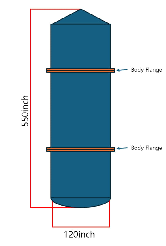
We are designing a low pressure vessel with body flanges. The internal pressure is 7.5 psiG
This would correlate to API 620 for low pressure vessels.
However, unlike API 650 there is no body flange calculation.

Thus we are using ASME Section VIII Division 1 calculation for pressure vessels,
and now the flange thickness calculated is much too thick for our design.

We are wondering if body flange thickness can be calculated according to atmospheric standards for this tank.

Any insight into this would be greatly appreciated.
 
Replies continue below

Recommended for you

Have you looked at TEMA flanges and design. I know that's heat exchangers but they design large low pressure connections.

What sort of body flange are we talking about?

Drawing?
sketch?
size?
Shape?

Remember - More details = better answers
Also: If you get a response it's polite to respond to it.
 
If you will be certifying the tank to API 620 I think you'll need to meet 5.20.3.

Not sure how you conclude "... the flange thickness calculated is much too thick for our design". If your calculations arrive at a certain thickness how can that be too thick, or do you mean too expensive? As you are designing a custom flange you should be able to adjust the dimensions and bolting to reduce the thickness somewhat.
 
OP, not sure what Codes / Standards you need to meet if any, but:

Can you use AWWA flanges?

Custom design flanges can often be thinner when designed using full face gaskets.

Regards,

Mike

The problem with sloppy work is that the supply FAR EXCEEDS the demand
 
How big is the tank?
Last I checked, API-620 is specifically for "field erected" tanks, and if this is a shop tank, you already have one deviation. If you're doing a non-code tank using API-620 for design purposes, then you should be able to deviate to use the AWWA flanges or API manway flanges.
One thing helpful for ASME flange design is that using stronger bolts increases the flange requirements, so using A307-B bolts may reduce the design requirements.
I don't remember the current status of flange-rigidity requirements, but if you're allowed to waive that based on previous experience, and AWWA flanges or API manways are known to seal in that size and thickness, that should be good enough to waive that requirement.
You say "unlike API-650", there is no body flange calculation but I'm not aware of any body flange calculation in API-650 either.
 
LittleInch, thank you for the suggestion. I believe our application has too large of a diameter for TEMA.

Geoff13, thank you for the suggestion. We have made quite a lot of adjustments without avail I will attach some dimensions below.

SnTMan, thank you for the recommendation. I will look into it. What I see is that in Table 2 Class 2B for up to 86psi, our ~120in inner diameter correlates to 2.75inches, which is much better than our 6.25inch calculation from ASME Sec 8 Div 1. However, I think AWWA might be for water at atmospheric temperature. I will attach some details below.

JStephen, you are right, we intend to shop fabricate, so API 620 may not be even an option. I will also look into the bolt specifications. I may have been confused on the existence of API-650 flange calculations.

For further details on the tank design,

- 550inch height, 120inch inner diameter
- 2 Flanges at 120inches from bottom and 360inches from bottom
- Cone shaped top head, dishhead bottom
- 140F operating temperature
- 7.5 psiG (Gauge pressure) operating pressure
- Contains phosphoric acid (The vessel operates P4 (white phosphorous) combustion and hydration reaction at the top of tank)

All aspects when calculated according to ASME Section VIII Division 1 is satisfactory except the 2 body flanges
Attached is a terrible drawing for reference, due to NDA and what not
Screenshot_1_bk1285.jpg


ASME calculations result in flange thickness of 6.25 inches
Atmospheric tank calculation shows flange thickness of 1.5 inches


Thank you all for your kind suggestions. Any further insight based on the above information would be incredibly appreciated.

I hope you all a great day.
 
Seems like I've seen a couple of tanks with bolt-on roofs, and they used smaller bolts and more of them than a normal flange. That would be one approach to try- maybe 5/8" or 3/4" bolts and 3" or 4" wide flange.
Another possibility would be to put stiffeners/gussets on them, which moves you out of the normal flange design process.
On larger tanks, I've had problems getting normal F&D heads to work under API-620, even heads that were clearly adequate per ASME would calc out as overstressed with API-620.
The contents sound relatively hazardous, so I'd be inclined not to skimp on design in this particular case, though.
 
Don't get confused about the Title "FIELD" in API 620 or 650. If size is small, normally 18' diameter and small, and short, we get it shop fabricated for better quality, regardless API 620 or 650.
I have a water tank with bolted body flanges, the same as the sketch. Supplier did the flange design per whatever the water code is.
If you want to use Appendix 2, I have done large diameter flanges at 1450 F as attached. The key to reduce flange thickness is the gasket width, bolting size and quantity. More bolting and smaller diameter is better. There is a standard bolting spacing vs. bolt size, use that as reference. Gasket width not to exceed 1" is better. Wider is not better. Keep gasket and bolt hole close to ID to reduce bending moment, making hub longer, and a short thicker section (1' or 2' long)for small end will help. Must check rigidity per code. Many factors to play around and optimize.

DO NOT use gussets/ stiffeners as suggested by others. You will regret doing so. The gusset/stiffener can cause local effect due to expansion/ contraction from welding and environment that FOF may not be true flat around and you will get leaking here and there, and no way to stop it.
Standard flange B16.5 B16.47 which is quite rigid that to install gussets is fine to resist rotating force from agitator that can damage the nozzle to shell junction.
 
 https://files.engineering.com/getfile.aspx?folder=a5b503f8-9481-480c-8e65-cd4e5704b152&file=flange_design.pdf
API 650 has specific provisions for shop-fabricated tanks (see Annex J).
API 620 does not. I point that out, as if you take exception to the standard there, you can logically do so elsewhere as well, not to say it ought not be done.
One issue with API 620 and shop fab is that the required pressure testing assumes that the tank is anchored in the field (assuming a flat-bottom tank) so you are pressure-testing the anchorage as well. If you have a suspended bottom, this is not so much an issue.
 
Due to low pressure, slip-on type flange will be your best choice if no process concern. In your case you do not need to use forging material, flange from plate won't cause any issue. Your flange thickness 6.25" in my opinion is excessive, compared with my case at 1450F, 5 psig and 108" dia with 304H SS forging which has very small allowable stress. Something not right in your calc.
If slip-on is used, I will further recommend to have a short ring (1' or 2' long) as the hub with thickness twice or more of the shell to gain rigidity, that you will sleep much better.
 
OP,
Have you looked up ISO 7005-1? The ISO standard combines both DIN and ASTM steels. The minimum pressure rating is PN 2.5 which is a bit higher than your design rating but what it will give you is that it will cover the 120 in flange dimensions with P/T ratings for different materiel group like B16.5 and MSS-SP-44.

Most importantly, your selection will be based on a published Standard.

As a quick note, while selecting the flanges, the working pressure won't be 7.5 psig, it will be 7.5 psig + liquid static head(ρgh).

May I ask you why you are going for flange connections in the tank shell? API 620 tank shell is welded construction. It's a tall vessel and there will be influence of external loadings on the flange joint from wind/earthquake (example: bending moment by Wind) and sidewall movement from external piping loads that will increase the risk of flange joint leak.

Remember, all flange design by any Standard (Sec VIII Div 1, Appendix 2, AWWA, ISO etc)is based only on pressure load and are not used in body flange. In your case, you need to consider other load factors.

GDD
Canada
 
If normal operating pressure is 7.5psig, max operating pressure = ?
Are there provisions for a high high pressure trip, which would be > max op ?
Upper Design pressure (UDP) would be at least 10psig..

What about min internal pressure - can it go sub atmospheric, and why not?

Agreed, why do you need these large body flanges ? Manholes for vessel entry are usually only 20-24inch dia.
 
Status
Not open for further replies.
Back
Top