Eng-Tips is the largest engineering community on the Internet

Intelligent Work Forums for Engineering Professionals

Flexible Assemblies (or parts)

Status
Not open for further replies.

drawoh

Mechanical
Oct 1, 2002
8,860
0
0
CA
I am preparing drawings of a cable. The figure is something I threw together so that I could ask a question.

TEST07-01_m9lqzj.png

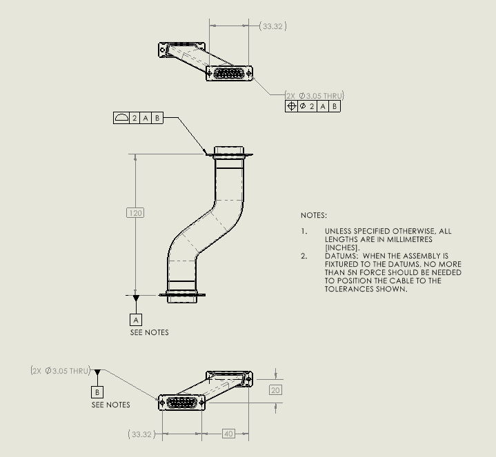
In the figure above, my datum features are the one receptacle. I am showing profile and positional tolerances for the opposite receptacle, but what I can really calling up is the force required to position it. The cable is flexible.

Would it make sense to call up profile and positional tolerances as zero? I am sure it will scare the heck out of the cable builder, but I am interested in meaning.

--
JHG
 
Replies continue below

Recommended for you

Hi, JHG:

According to your description, your datum feature A is incorrect. It should not line up with dimension 120 BASIC. Otherwise, it will have a different meaning.

Because your cable is flexible, the top receptacle has 6 degrees of freedom. Your BASIC dimension 120 controls 3 DOFs. So, the top receptacle has 3 remaining DOFs which you will need to immobilize.

Best regards,

Alex
 
jassco,

No, I have put positional tolerances on the holes of the second receptacle. Everything is constrained.

--
JHG
 
Hi, JHG:

No. You can't position the top receptable as it has nothing to do with the bottom receptacle other than dimension 120 BASIC. How can it be positioned if there is nothing from datum feature A & B that supports the top receptable?

In another word, you can't talk about positioning if your datum A and B do not ARREST the features on the top receptable.

Best regards,

Alex
 
Your force requirement seems under-defined to me.

To hold the free receptacle in place you need to apply forces in X, Y and Z directions and moments about each axis.

It also doesn't seem useful. If you don't meet the requirement on the first try what happens? The tech exercises the cable until things loosen up and it "passes", right?

What functional requirement are you really trying to check?
 
I'd guess you would want the pins and sockets to mate properly once in the position shown, and not have any of the wires break, or pins/sockets to pull out of the housing, and that a normal human with normal grip strength be able to make up the connection. Would a continuity check of the cable once connected be sufficient to verify a "good" installation?

If not, do you have a preferred method to measure the force required? What about moments? Lotta stuff undefined. As far as specifying both a position tolerance, and a force tolerance (no greater than), no I don't think you have overconstrained the problem, as long as you understand that the vendor can possibly bias their force test to get a passing result, i.e. keep the fasteners loose until the datums are in the right position, then snug up the screws...which is how every dsub cable I've ever connected has been made up.
 
The datum feature symbol does not line up with the dimension so it applies only to the connector surface.

As usual the standard doesn't say how much offset is required, but it is clearly not aligned. It could be more not aligned.

There should be a basic dimension between the controlled holes to use the position tolerance as 2X.

The top connector is already arrested, just the second hole is not completely defined.

I would say the force requirement isn't bad as "no more than" is sufficiently explicit. The missing item that I have had more trouble with cables from is torque to flex the cable in the hard and easy bend directions; twisting isn't usually a fight.

I would indicate that no tools be allowed in the process, hands only. This may make things more difficult to measure, but next up is dealing with someone grabbing channel-locks and giving it a go.

These limits are a real effort to establish. The question is how much load is getting put on the pins and and on the wires and on the sleeving and what is the limit to that. Your FEA guy will not talk to you if you want to find this out. If you take it to human factors, they are unlikely to ever shut up about how it should be handled, unless they are old and near retirement.

Having been exposed to "flexible" cable, I have noted that shrink sleeving, particularly adhesive shrink sleeving can result in a surprisingly stiff cable. I used to have a piece of 50 twisted pair cable that could be used as a baseball bat even though all it had inside were teeny telephone exchange wiring.
 
3DDave,

Both connectors in this are panel receptacles. You mount one receptacle, and force the other one into place on the opposite panel. The required force should not exceed five Newtons. Otherwise, you are describing my problem. I have wires, shielding, and shrink wrap tubing, all of which make the cable semi-rigid. If it takes a lot of force to install both ends, we are likely to damage something.

--
JHG
 
The problem is going to be flexing the item backwards to get enough clearance to fit into that gap. It's painful to have nominally aligned connectors like that and no slack with a stiff assembly.

I am not sure I see a good path out of the corner where the room has been filled with alligators.

The typical answer would be to use right angle connectors at both ends with an amount of arch to the cable, allowing a great deal of flexibility to install it and depending on the rigidity of the panels to provide stiffness in the direction perpendicular to the panels.

 
Status
Not open for further replies.
Back
Top