Continue to Site

Eng-Tips is the largest engineering community on the Internet

Intelligent Work Forums for Engineering Professionals

  • Congratulations IDS on being selected by the Eng-Tips community for having the most helpful posts in the forums last week. Way to Go!

Flexible Power Transformers 4

Status
Not open for further replies.

RRaghunath

Electrical
Aug 19, 2002
1,729
GE developed a flexible power transformer which makes it possible to change the %Z at site. GE link below for ready reference:
I was just wondering how this became possible now when it wasn't (possible to adjust %Z of transformer in the field) all these decades!
I would like to hear from experts on the forum.
Thanks.
 
Replies continue below

Recommended for you

Many years ago, a device called a wireless reactor was used to parallel transformers with unequal impedances.
It was a stack of laminations mounted on the cross arm beside the transformer through which one secondary conductor was passed, to increase the effective impedance of the transformer.
Think CT core with no winding.
Now, i'll look at what GE is offering.

--------------------
Ohm's law
Not just a good idea;
It's the LAW!
 
OOps.
Document link said:
We’re sorry that the document you requested cannot be found.
This may be a regional thing. Are you able to cut and paste some information?

--------------------
Ohm's law
Not just a good idea;
It's the LAW!
 
I think GE uses DC current to regulate the impedance of transformers.
In our local grid, we use controlled shunt reactors to regulate voltage and reactive power in the grid. A controlled shunt reactor has a special control winding, which is located at the same core as a network winding. The principle of operation is that through this control winding flow DC current and impedance of this reactor depends on the level of DC current. If DC current has a high level, the impedance of the reactor decrease and the reactor produces more reactive power into the grid and vise versa. DC current saturates the core and it leads to decrease impedance.
So I think a similar method was developed by GE.
Also you can read about CSR:
 
I suspect that they are using two saturable reactors in parallel with opposite polarity DC bias.
One reactor would be active on the positive half cycle and the other would be active on the negative half cycle.
This may be a very old principle, magnetic amplifiers, recycled and re-engineered for a new application.

--------------------
Ohm's law
Not just a good idea;
It's the LAW!
 
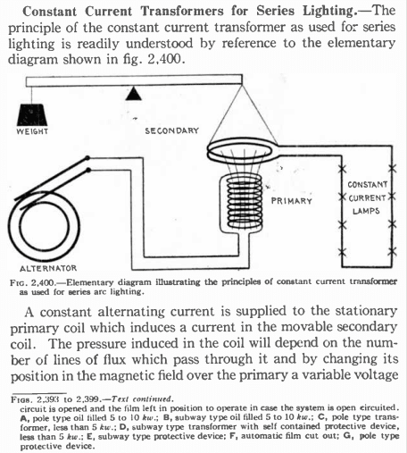
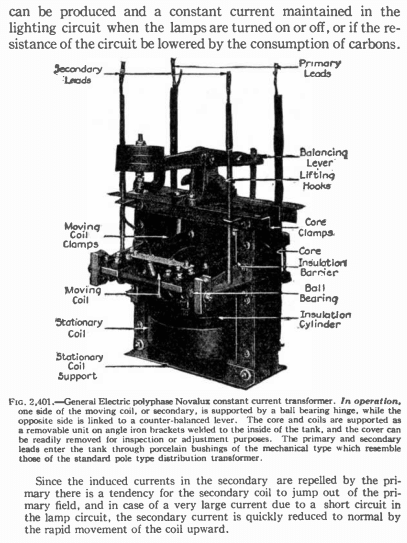
Here is a really ancient example. Constant voltage input, and approximately constant current output, by moving one of the transformer coils. Once used for street lighting.
Screenshot_from_2021-10-29_18-15-55_a8hjq1.png

Screenshot_from_2021-10-29_18-25-28_p92mon.png

Audel Electric Encyclopedia 1935 p1693 and p1694.

Note this is a GE example from long ago.
 
Reading the advertisement, I guess adjustable impedance might be useful in reducing circulating currents. I doubt the availability of adjustable impedance will do much to lower the huge cost of transmission transformers, or better their lead time. Better control of parallel flows might improve system efficiency
 
Constant current lighting systems are still used for airfield lighting, or at least were not all that long ago.

I’ll see your silver lining and raise you two black clouds. - Protection Operations
 
Protection of series lighting circuits is interesting.
A short circuit is of no consequence on a series lighting circuit.
An open circuit is a fault condition. open circuit voltages may rise to several thousands of Volts.
Shorting buttons are used across lamps to complete the circuit in the event of filament failure.
Lamp protection buttons would fail shorted at around 100 Volts.
The original series circuits used incandescent lamps. In later years, series mercury vapour ballasts were developed and series circuits could be used with discharge lighting as well as with incandescent lighting.
Constant current transformer secondaries were protected by buttons that would fail shorted at several thousand Volts.
Currents could be 6.6 Amps, 7.5 Amps or 20 Amps. (I remember one other common voltage but not what it was. In the range of 6 Amps to 7.5 Amps.)
20 Amp circuits were used alongside rail trolley lines.
Consider: 400 Watts at 20 Amps = 20 Volts. The 20 Amp filaments could be seen to warm up and cool down similar to a toaster element but much faster. 20 Amp filaments were very robust and able to withstand the vibration caused by passing rail trolleys.
Series lamps used a special mogul socket.
The center contact was spring loaded to maintain good contact at the relatively high amperage.
The center contact also had a protruding tab. When the lamp was inserted, the tab was held down. As the lamp was screwed out, the tab was forced upwards until it contacted the bottom of the shell, to short out the lamp holder and keep the string in service.
Most of the circuits were ungrounded, but many developed grounds due to failure of the old insulation.
The guru of the series circuits had a little black book with information on every series circuit in the city.
Every year he would check each circuit for grounds.
If a ground was detected, he would go to work to locate the location.
He would start by breaking the circuit and checking until he located the run (between two lamp standards) with the ground.
Then he would bring out the Wheatstone Bridge and calculate the exact location of the fault. He would then record the information in the little book and leave without repairing it.
Eventually, it may be years later, a second ground would develop on the circuit. All of the lamps between the grounds would go out so the general location was easy to find.
The two grounds were often several city blocks apart.
John would check his book to see which ground he had located.
He would then proceed to the location of the latest ground and bring out the Wheatstone Bridge (Or the Electric Banjo as we called it).
John would carefully calculate the location of the new ground and record it in the book.
He would then instruct his helper to load everything into the truck.
When the truck was loaded, he would instruct his helper to drive, giving him block by block instructions.
When they reached the location of the first ground, John would get out of the truck and measure off so many feet from a lamp standard and tell his helper;
"Dig here."
Sure enough there would be a failed cable.
John had a drinking issue, but by keeping his information secret, he was able to drink his way to retirement without being fired for one of his escapades.
Like the day when an engineer (a small man) wanted to talk to John (a large man) out in the field.
The engineer saw john sitting in his truck and walked over and opened the door.
He didn't realize that John was passed out, drunk.
John fell out of the truck on top of the engineer and pinned him to the ground, still unconcious.
Incidents like this were covered up as management had no-one trained to replace John.
You can't make this stuff up.
I worked with John for one day. We set up the Electric Banjo and located a ground on a cable.
I watched over John's shoulder and got the reading.
As John was calculating, I was calculating.
"John, is it 15 feet to the ground?"
"NO! It's 110 feet."
"110 feet plus 15 feet on a 125 foot run? that works for me."
That was the last time that John let me near his truck.


--------------------
Ohm's law
Not just a good idea;
It's the LAW!
 
1) Thank you Raghu & thermionic1 for bringing attention to this product. This, as per their claim, is a multi-voltage ratio and variable impedance transformer. The multi-voltage ratio is nothing new.; varying impedance by using series reactors (esp in the tertiary circuit) is also not a novelty. Here they use a new concept for impedance addition by adding or removing compensated winding sections in the same core limb. The question is do the grid have so much benefit ( impedance variation from 4 to 14 %) compared to the extra cost and complexity introduced compared to a simple conventional auto-transformer?

2)Variable frequency transformer ( or Rotary transformer is a product developed by GE around the year 2000) In reality it is not a conventional transformer, but a generator with moving parts. A couple of units are in service and Chinese engineers have written a book on this product.
Gesong Chen, Xiaoxin Zhou, Rui Chen, Variable Frequency Transformers for large scale power systems interconnections- Theory & Application, John Wiley &Sons, Singapore, Pages 249, 2018

3) Transformer manufacturers are introducing new products(with slight variations)from time to time. But its future is ultimately decided by the user. Remember the sad story of Dryformer introduced by ABB in the fag end of last century - large HV transformers without paper and oil, a completely dry product using XLPE cables for winding.
 
Status
Not open for further replies.

Part and Inventory Search

Sponsor