Eng-Tips is the largest engineering community on the Internet

Intelligent Work Forums for Engineering Professionals

Float switch issues

Status
Not open for further replies.

Patattack

Electrical
May 9, 2018
3
0
0
IT
Hi.

Sorry I'm new to electrical circuits, I am sure that my problem can be solved by a single over the shelf module, but I can't seem to find one.

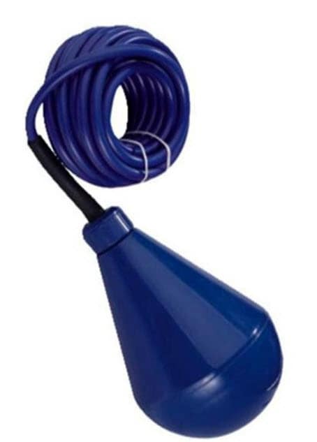
I have a water tank with a float switch, and this float switch is connected to a contactor. At points of filling or draining, and the water level reaches the float switch, the switch turns on and off incredibly rapidly, cauing a real commotion at the contactor.

I was just wondering, is there some sort of module that only allows an 'on' signal from the float switch if it is constant for a set duration of time (say, for example, 5 seconds?) and not allow any current through if that threshold has not been reached?

Thanks in advance guys,

Patrick
 
Replies continue below

Recommended for you

The conventional solution to this problem is to use two level switches, one to latch the contactor 'on' at a pre-determined level and the other to de-latch the contactor at a second pre-determined level. The basic circuit is the same as a two-button motor starter but with level switches in the positions of the start and stop buttons.
 
What Scotty sez is a fine solution but, in reality, you should just put in a properly functioning float switch correctly. Modern float switches are all designed with a large amount of hysteresis to completely prevent what you're seeing. If installed correctly that simply can not happen. They typically have a conductor ball that has to roll thru an hourglass shape to make contact and to shift the center of gravity further to the on or off position. Then, until the tank level has changed by more than a foot (and this is greatly adjustable) the reverse can't happen.

However, if this is some sort of small couple-of-gallon lab type tank with a rigid float and switch then use two floats and a flip-flop scheme as Scotty suggests.

Keith Cress
kcress -
 
Depends on what you're controlling the level of. We have a lot of the schemes I described on sumps around the plant, typically 20' deep holes fully of oily water. Pretty reliable, although we're slowly migrating to contactless level transmitters and a couple of trip amps configured to mimic the old scheme.
 
The amount of hysteresis is usually determined by the amount of cable left un-attached between the float ball and where the cable is attached to the structure. However the OP stated a float switch which could be of the type where the float rides up and down a rod. these types typically do not have much hysteresis. If this is the case then the switch is the wrong type for the application.
 
Hi Pat,
If I understand your situation; you are using (what we here in Canada) call moose-ball type of level-switch. Correct?
If this is the case then it is common to use two moose-balls for control of a pump. The higher unit initiates the contactor to pull-in and is then sealed in by an aux contact from the starter. The lower unit will drop out the starter coil.
BTW, actions on the moose-balls are important (I usually will spec a moose-ball with a Form-C contact).
I have never seen a pump-level control scheme with only one moose-ball.
GG
2018-05-11_19-23-00_bsqyp7.jpg


"I have not failed. I've just found 10,000 ways that won't work." Thomas Alva Edison (1847-1931)
 
While I agree with others in that two float switches is the norm sometimes there isn't the room in which case one switch and a timer works just as well.
Level rises to switch, pump starts and is latched on by a timer to keep the pump on long enough to well clear the switch.

The pump should have a check valve so that when it stops the fluid doesn't run back into the tank
 
A more direct answer to your actual question, Pat is yes.
It is typically call a "Debounce" circuit.
It prevents transient signals from affecting normal operation.
It can be program logic or relay logic.
In your application, for the sake of economy and simplicity (assuming your application uses only one switch contact which is not adjustable),
use the switch signal to "fire" a delay on relay. Wire the relay normally closed contacts into the contactor coil for the pump motor.
When the fluid level rises to the float, the power will be removed from the relay but it will not drop out turning off the pump until the programed time has elapsed.
The time increment is usually set by dial or dip switch.
This should solve your problem.
 
Status
Not open for further replies.
Back
Top