Eng-Tips is the largest engineering community on the Internet

Intelligent Work Forums for Engineering Professionals

  • Congratulations waross on being selected by the Tek-Tips community for having the most helpful posts in the forums last week. Way to Go!

Flow reduction problem over nozzle ?

Status
Not open for further replies.

RedSnake

Electrical
Nov 7, 2020
10,486
0
36
SE
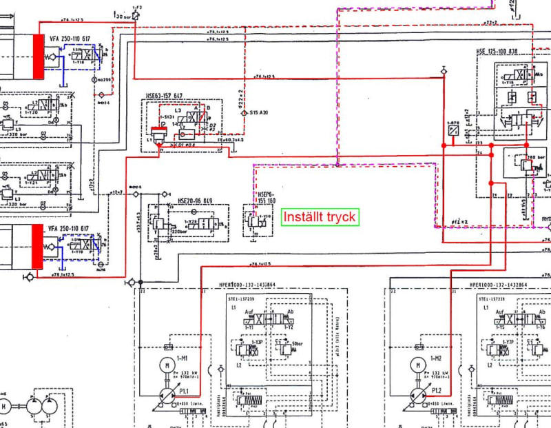
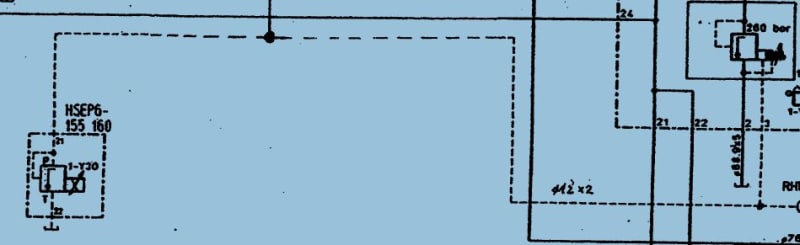
My problem is I have this pressure relief prop valve.
RS416-10/315/0,7
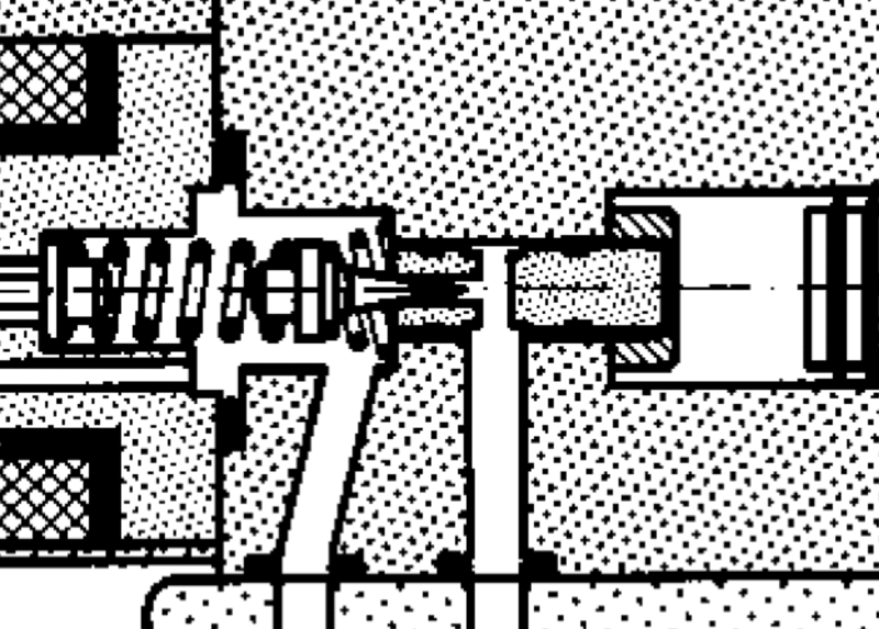
In the documentation it’s says it the maximum flow is 6 liter/minute depending on the nozzle D12.
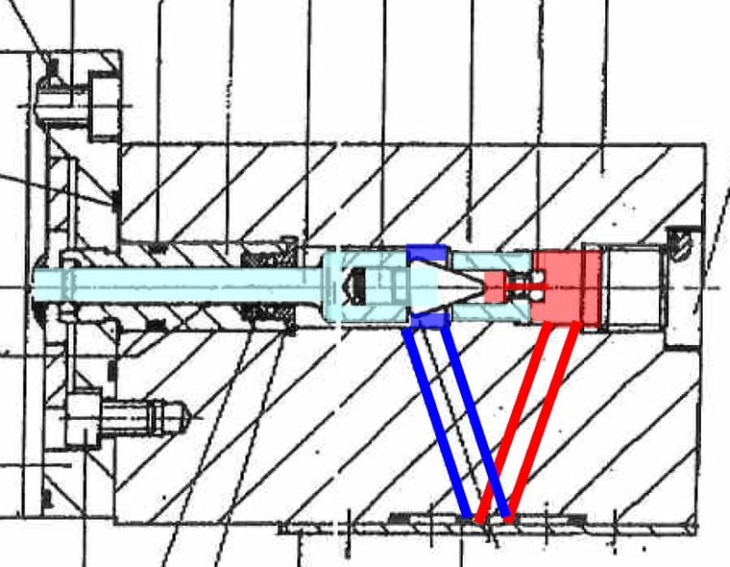
Which is placed between the P port and the valve cone and then to the T tank.

valve_upiujb.jpg


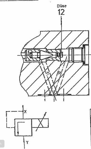
You can buy it without the nozzle but ours have the R900008869 Nozzle 0.7 M4x7 MS RN115.38
The nozzles available are 0.7 mm, 0.8, 1, 1.1, 1.2, 1.4, 1.5, 1.6 mm
Since I cannot find any information in the document about the area without a nozzle,
My first assumption is that you cannot use the valve without one.
My second assumption is that the flow 6 l/min is the flow with a 1.6 mm nozzle.
My third assumption is that the flow is linear against the area, which means that a flowchart would look like this.
3 liter/minute and 1 mm2..

Nozzle Area Max Flow
0,7 0,38 1,15
0,8 0,50 1,5
1 0,79 2,34
1,1 0,95 2,84
1,2 1,13 3,38
1,4 1,54 4,59
1,5 1,77 5,27
1,6 2,01 6

Someone please tell me if this is correct!
It feels a bit to simple, makes me think I have missed or misunderstood something?
Something that adds to this confusion is that the valve is constructed in 1982, and someone working for the manufacturing company had a couple of years ago, looked at our valve and written that the maximum flow is 4 liter/minute.
And I do not understand how he came up with that number [ponder]
This is not my area of expertise..

Best regards A


“Logic will get you from A to Z; imagination will get you everywhere.“
Albert Einstein
 
Replies continue below

Recommended for you

Unfortunately, I have no data for that.
It is actually a pilot valve for the real pressure valve(260bar) which has a working pressure between about 30-252 bar.
The pilot valve in question is 1-Y30 HSEP6-155 160 (max 315 bar)
My assumption are that it to has a working range P between 30-252 bar and on the other side T against the tank my assumption is that the pressure is 0 bar ?

Hyd_wyhxkt.jpg


Best Regards A

“Logic will get you from A to Z; imagination will get you everywhere.“
Albert Einstein
 
You are correct that T is 0 in your drawing. However if T is anything but 0 it simply adds to the opening pressure.

I am looking at your valve drawing to understand the purpose of the orifice.

If I had to hazard a guess the orifice sets the minimum flow rate through the valve when it is the shut position. Once set pressure is reached, the valve becomes proportional to maintain the set pressure value and will vary flow rate as a result.
 
I posted this image in your other post. It shows the cone valve in more detail. This one does not appear to have the orifice. In your case the orifice would appear to limit the maximum flow.

Screenshot_20210127-134932_zknm7d.png
 
Well as I se it all oil have to go through the nozzel.
First it has to pass the nozzel and then the valve cone.
If I put max power on the coil the valve cone is shut, no oil goes through then I have 260 bar at the combined safty and pressure relife valve.
And if I set 0V (ca 0 Amp) it is open, it drains out all oil. pressure is drops to 0 bar at big valve (260bar)

But then is the question how much is the maximum flow with a 0.7 mm nozzle if max is 6 l/minute ?
I can download the hole valve data document, but it is in German so I don't know if it would help you ? ;-)


/Red


“Logic will get you from A to Z; imagination will get you everywhere.“
Albert Einstein
 
My problem is that this valve can't be bought so we need to exchange it.
And my "esteemed" mechanic hydraulic colleagues have decided that we need a valve that can handle 4 liters per minute.
But they can not produce a calculation for this.

The only valve that is available have to high pressure 350 bar instead of 315, and whit this valve it will not be possible to adjust the zero and max point with the prop card.
This new valve they are proposing is adjusted from the factory and have a maxflow at 5 liter per minute.

The other valves available have a max flow of 2 liter per minute and the pressure 315 bar and can be connected to our old prop card or a new one, and can be adjusted as before.

When I look at the data of the old valve see attached file above, it seems to me that this 4 liter per minute is not correct with a 0,7 mm nozzle.
But I just want to make shore that this is correct.
My thought is that old pressure relief valve have a maximum flow of 1,15 liter per minute.

Nozzle 0,7 Area 0,38 = 1,15 liter per minute

Nozzle 1,6 Area 2,0 = 6 liter per minute

So if anyone are able to confirm or dismiss this it would be nice..

Best Regards Anna


“Logic will get you from A to Z; imagination will get you everywhere.“
Albert Einstein
 
A big question is what is the purpose of limiting flow at 1.15. I haven't exercised fluid dynamics in a while but it seems reasonable that flow rate through an orifice would be proportional not the diameter as the velocity is high and length is short so the boundary layer effects should be miniscule. So I believe you are correct.

The next problem is that you're buying a valve with a maximum rated flow which has little to do with flow control. A 2 lpm relief should be able to flow 2 lpm with minimal pressure drop versus your valve with an orifice that limits flow to less that 2 lpm.

However, your valve is proportional so limits can be electronically programmed. That is, until the electronics fail. These proportional relief fail open. Is there any risk to having more than. 1.15 lpm through your system?
 
I will try to explain the function as I see it.
BTW I do have had 80 hours of basic hydraulic practical and theoretical education but that is aged ago and all my books are at work..

My first thought was that it was a ordinaire pressure relief valve but since it does not seems to have a spring !?
I think the function is that I adjust the flow rate over the cone depending on how much it opens or closes building pressure at P. So it is actually more of a proportional "flow" valve.
In the data for RS416 I saw that the flow over the valve must not be less then 2 lpm.

If I would put OV or at a power loss the pilot valve (RS416) will be opened by the pressure in P and when the pressure drops this opens the 260 bar valve that we call "Kalle" in English it's the same as Charlie :)
When Kalle opens all the flow from the pumps (2100 lpm) will go over Kalle directly to the tank which makes the pressure go 0 bar at P on the pilot valve 1-Y30 (RS416) since the pressure at P comes from the main pumps via Kalle.

So if you put in a valve with max flow 5 lpm I believe what will happen is that Kalle will open much faster with a hell of a bang, it is not very quiet when it opened to day either, it might not go 4 times as fast but it wont be good for the equipment.
Or am I wrong?

The same applies when regulating it to a specific pressure it will take a bit longer to reach the set pressure, but I think that, that is not the big issue here.

Both the 5 lpm 350 bar valve that the mechanics thinks is the only one that is available and the one only one we can and must use.
And the 2 lpm 315 bar that I wont (there are more of them to choose from).
Both have the optimal regulating flow at 0.8 lpm and the construction is the same.

The big difference electrical is that the possibility to adjust the 0 and max is gone.
And the pressure regulation will be less accurate with the 5 lpm 350 bar.
Today I have 315 at 27648 with the 5 lpm I will have 315 at 19907.
And we don't want more out then 265 bar, that is for adjusting Kalles safty spring (260 bar)
The press only uses 252 bar.

Reglering_icw5ry.jpg


And what the risks are with putting 350 bars on Kalle instead of 315 I think we must discuss in the next chapter.
The machine safety regulations and work environment legislation chapter.
I am getting writing cramps [smile]

And thanks for helping Tug [thumbsup2]

Best regards Red


“Logic will get you from A to Z; imagination will get you everywhere.“
Albert Einstein
 
What do we have... a max flow 6 lpm with nozzle 1.6 mm A = 2 mmm2
Installed nozzle 0.7 mm A = 0.4 mm2 flow ?? lpm

strypning_xdemfa.jpg


Since pressure drop, density, and flow factor is the same in both cases I replace them with x
1.6 Nozzle
6=2*x
x=6/2
x=3

0.7 Nozzle Q= 0.4*3 = 1.2 lpm

What can go wrong with this ?? ponder
Answer..
That the length L of the choke in the flow direction is negligible compared to other dimensions.
And when does this statement apply ????????????????????????? seems like a very unprecise and fluffy condition to me [sadeyes]

waross said:
The only thing that you are changing is the diameter.
0.7mm/1.6mm = 0.4375 diameter ratio.
0.4375^2 = 0.1914 area ratio.
6 lpm x 0.1914 = 1.148 lpm ???

Yes that is the same result as mine.
But someone have sometime, somewhere stated that the 0,7 mm nozzle gave 4 lpm I do not understand why/how??

The only thing that can change this is the length of nozzle 7 mm don't know how much of the length is actually dia 0.7 mm on the inside.

Best Regards A [bdaycandle]

“Logic will get you from A to Z; imagination will get you everywhere.“
Albert Einstein
 
Hello,
To manufacture a proportional pressure relief valve, we know the maximum force of the coil. Then we propose a maximum pressure range which generally goes from 20 to 315bar. For this we change the diameter of the needle seat. Normally there is no jet upstream of the needle.

In the supplier documents we find the pressure drop of these pressure limiters without any effort on the needle. For example at ATOS valve RZMO or VANDFLUH valve BDP. You can know the seat diameter with this formula: Q (l / min) = 0.5 x d² (mm²) x dP (bar) ^ 0.5.

Your "kalles" main pressure relief valve has a substantially constant pilot flow whatever the pressure required. It depends on the diameter of the internal pilot jet and the setting of the main spring (approximately 4 bar).

The only advantage of the jet upstream of the needle of your proportional pressure limiter is to avoid "cannon shots" when you cut the proportional valve without a ramp. Without this jet and if your electronic card lowers the setpoint slowly, there will only be a problem in the event of a sudden electrical cut in the current to the coil.

This ød jet has 2 drawbacks: a) Higher pressure peaks if the main circuit is suddenly closed. b) The minimum pressure in the circuit will be 4bar for the main "kalles" spring + (4l / mn / (0.5 x d² (mm²)) ² + catalog pressure drop of the proportional valve.

So if your electronic card has a pressure drop ramp, you could fit a commercial valve without an upstream jet. The catalog max flow is not very important except that the minimum pressure will be a little higher.

Personally, on presses or shears up to 6200l / min at pumps where we are not looking for an intermediate pressure, we replace your proportional pressure limiter by an NO solenoid valve and a nozzle that we calibrate to have 20 to 25bar minimum pressure. And we have rapid decompressions without "cannon shots".
 
73lafuite I will give your post a better read tomorrow when I am working.
Okay Thanks.
My problem is that the mechanics wont to replace this RS416 pressure relief valve, with one that has 7 liter per minute flow at 0 and no card directly.
But directly connected to my PLC analog output and I am trying to tell them this is not going to work with the program that is.
And making a new PLC program for one without a prop card is a huge job.
This "kalle" is also used for regulating the pressure in the press cylinders between 0-252 bar > 0-8000 kN.
Every time the cylinders turn from up to down and when stopping in top position the valve will go to O and every time someone brakes the safety enclosure.

What we have is this RS416-10/315/0,7 see attached document. 315 bar min 2 liter per minute max 6 liter per min depending on nozzle.
What the mechanics wont is a valve 350 bar, 7 liter per minute, no prop card.
and I want a 315 bar 2 liter per minute, with our old or a new prop card.

And they do not now how some derived at the flow of 4 liter per minute for this old valve??.
My calculation makes it 1,15 liter per minute.
I do not know what's right or wrong here. [ponder]

We actually do not have all the data we need to actually make a proper calculation.
Witch is a another reason to way a try to convince them to try with my valve first with less flow at 0V.
We cant establish that the machine safety hasn't been changed if we put in a valve with more flow and higher bar.

Best Regards A

“Logic will get you from A to Z; imagination will get you everywhere.“
Albert Einstein
 
With Normally there is no jet upstream of the needle. do you mean with no nozzle ?
With Without any effort on the needle. do you mean fully open?

Best Regards A


“Logic will get you from A to Z; imagination will get you everywhere.“
Albert Einstein
 
With Normally there is no jet upstream of the needle. do you mean with no nozzle ? Yes, if we want to have the maximum flow, why add a nozzle in series?

With Without any effort on the needle. do you mean fully open? Yes
 
Yes, if we want to have the maximum flow, why add a nozzle in series?
This valve RS416 is manufactured 1978, I think the reason is that the opening speed wasn't possible to adjust in any other way back then and it was probably also possible to use the same valve for different applications instead of having many.

The only advantage of the jet upstream of the needle of your proportional pressure limiter is to avoid "cannon shots" when you cut the proportional valve without a ramp. Without this jet and if your electronic card lowers the setpoint slowly, there will only be a problem in the event of a sudden electrical cut in the current to the coil.
The proportional card is only a power amplifier you can adjust the Zero point and Max point "tipping" the curve and
the oscillation.

there will only be a problem in the event of a sudden electrical cut in the current to the coil.
That is done every 4 second when driving the machine.
The new pilot valve must not open "kalle" faster.
So I would say we have a problem.[sadeyes]

Best Regards A


“Logic will get you from A to Z; imagination will get you everywhere.“
Albert Einstein
 
Good evening,
If you have one or more variable flow pumps and you have a solenoid valve which puts these pumps at zero flow when you cut off a movement: The pressure drops to 20bar which is the value of the load sensing spring. In this case your pressure limiter "kalle" which receives a setpoint = zero must remain around 25bar. Otherwise the pump(s) remain at maximum flow and when the next movement starts, you will have a pressure peak. So that would explain the nozzle upstream of your proportional valve. You could therefore use a proportional valve on the market and add a nozzle upstream so as to have about 25bar without current at the proportional valve. A recording of the pressure in the pressure manifold will tell you more.
 
God evening to you too.
If you have one or more variable flow pumps and you have a solenoid valve which puts these pumps at zero flow when you cut off a movement:
The pumps goes to zero when the pilot valve does, in most cases.

My first priority is to convince my colleagues who wants to make this test.
To do it with a 315 bar 2 lpm valve and the old prop card.
Instead with their 350 bar 7 lpm valve without the prop card.
Then will see what happens.
But I am not shore if my assumptions are correct.
My calculation makes the flow in the old valve 1,15 liter per minute.
And if you put in a 7 lpm it will open with a hell of bang.
Right or wrong ?

Hyd2_gyx55g.jpg


Best Regards A

“Logic will get you from A to Z; imagination will get you everywhere.“
Albert Einstein
 
Maybe a little bit of a late respons.

I cannot confirm your flow calculations for the valves since i dont know the pressures that the manufacurer/s has used when specifying flow. Maybe its specified in the datasheets. Otherwise we cannot know without asking the manufacturer.

But yes, if you use a valve with higher flow the main relief valve ”Kalle” will close faster. However you can problably use a external orifice to slow it down.

If you have old prop cards they might be obsolete and upgrading could be a good idea. A lot of manufacturers has amplifier solutions with max limitation, etc. Eg. Parker pzd.
So dont get hung up of the Max pressure for the relief valve.

If you are concerned and want to have higher safety, a fixed relief valve can problably be used paralell to the proportional relief valve.
 
Status
Not open for further replies.
Back
Top