Eng-Tips is the largest engineering community on the Internet

Intelligent Work Forums for Engineering Professionals

Fluctuating Thermocouple Readings

Status
Not open for further replies.

123MB

Electrical
Apr 25, 2008
265
0
0
AU
Hi All,

We have a classic thermocouple issue as follows:

1) 10-off K-type 0-1100 deg C thermocouples 500m long connected to...
2) Non-isolated thermocouple converter with...
3) 4-20mA output from converter to a DCS/PLC.
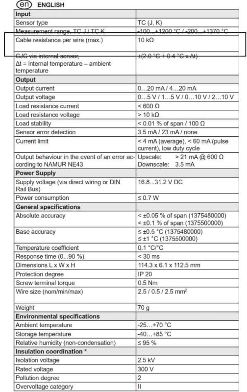
4) The thermocouples are ungrounded, metal sheathed with a lead to lead resistance of ~2-4k ohm.
5) The thermocouple converters and DCS/PLC are housed in a stand-alone solar powered control panel with a DC battery bank, solar charge controller, and small PV array, providing DC power for the system. The DC power system is unearthed.
6) The hot junction is at the bottom of a well, from where the metal sheathed thermocouple wire comes to the surface where it is extended via a potted connection to a thermocouple extension cable. The extension cable is not shielded.
7) The metal sheaths of the thermocouples are all unintentionally bonded together and to the metalwork by what is probably a relatively high resistance connection (they are all just touching each other and the cable tray they are ran on) but there is no proper low impedance ground connection (i.e. bonding of the sheath).
8) The DCS/PLC panel has a floating DC supply and we are not sure if the chassis of the panel is connected to the bonding system (i.e. cable tray, etc).

All thermocouple 4-20mA values fluctuate significantly (from +200% to -200% of the expected temperature within 30 seconds). There is even a thermocouple which is not down the well, it is just coiled up on the ground adjacent the cabinet, which exhibits the same behavior. This behavior coincides with the daylight hours which has led to the suggestion that solar charging is initiating the issue. In addition, the solar charging has been enabled and disabled and the malfunction disappears and reappears accordingly.

The charger has the ability to switch from fast-switching regulation (10KHz) to slow switching (<10Hz) and this has been implemented but it has not improved the situation.

Things I am considering trying next are:

1) To reduce potential for ground loops, ensuring the whole system is at the same potential by improving the bonding across the cable route, since it is not possible to isolate the thermocouple sheaths from the bonding system along their lengths.

2) Making a low impedance connection from each thermocouple sheath to the bonding system, i.e with a sheath bonding wire.

3) Grounding the 0V of the DC supply, so that any noise which is radiated onto the chassis or frame has a better return path to the source.

Any ideas?

 
Replies continue below

Recommended for you

OP said:
...from +100% to -100% of the expected temperature within 30 seconds...

That's an odd way to express variation or of temperature readings. If the temperature was 0°C, then would the variation go to zero?

OP said:
...thermocouples....with a lead to lead resistance of ~10k ohm.

Thermocouples? 10k ohm? A thermocouple is a metal-to-metal junction and the measured resistance should be effectively very close to zero, plus or minus any voltage being emitted from the junction.

Does the frequency of the issue match the PWM frequency of your solar change controller?
 
Hey there...

Yes I was rushing a little when I was trying to quantify the degree of variation. I actually meant to say -200% to +200+. The expected temperature is around 40 deg C, it is swinging between -80 and +80 deg C.

I do not know if the frequency of the issue matches that of the charge controller. The switching frequency of the charge controller is 10Hz now, I doubt that the PLC/DCS trend that I have access to would provide me with a comparable sampling rate.

And regarding the resistance, I was trying to specify the amount of resistance in the lead wires. The run length is quite long (500m). I don't know what size the thermocouple wires are, but I have measured the lead to lead resistance onsite and it is 4-6 kOhm, depending on the thermocouple. The converter/amplifier has a limit of 10kOhm per line, which I thought was quite high, but it must have a very high input impedance.
 
OP said:
In addition, the solar charging has been enabled and disabled and the malfunction disappears and reappears accordingly.

Try switching to a less efficient and quieter linear regulator for the solar controller.

Or use your noisy DC (solar) power to feed a very quiet linear power supply. Or float a big low impedance (lead acid) battery to ensure that the voltage is quiet.

An advantage to low voltage DC solar is that it could be somewhat isolated from ground (plus or minus safety and lightning protection). So hopefully ground loops via the power system don't have to be an issue.


Even a 500-meter run of 40-gauge wire would only be around 3-kohm, and I highly doubt you're using less than mid-20's gauge wire (so resistance will be <100 ohms). Whatever you're measuring, it ain't the thermocouple, and it ain't the connecting wire.

Dan - Owner
Footwell%20Animation%20Tiny.gif
 
Set the meter to all available different scales, to see if the resistance reading changes. Also, of course, reverse the meter leads. If either of these techniques change the supposed resistance measurement, then it may be an indication that the small voltage (current) being emitted from the thermocouple itself is impacting the meter's resistance measurement.

Plus of course, if the wires are picking up significant noise, then that may also confuse the meter.
 
With a good DVM try measuring the mv signal at the thermocouple converter. You should read around 1 to 2 mv. See if that voltage is varying. If it is, disconnect the thermocouple leads and repeat the measurement. Should give an idea where the noise is coming from.
 
... the sheath is 2mm diameter...Based on that I would agree the thermocouple wires themselves are about 0.8mm dia = 20 gauge. Using ~0.6 Ohms per double foot which equals ~ 300 Ohm.

The values measured on site are alot higher than this. Any ideas for the cause?
 
1. I'm another voice that says your resistance measurements make no sense. An isothermal thermocouple (both ends at the same temperature so that there's no gradient EMF) is typically an ohm or two (well, it's always that resistance but the EMF from a hot-to-cold junction gradient contributes to a resistance msmt error), so others' comments about the resistance is on target. T/C junction/lead resistance should be single digit ohms. That 10k ohm per line spec for the input leads of the transmitter is a really fishy spec. Most T/C transmitters get uncomfortable at more than 200 ohms of lead wire resistance.

2. Presumably 500m wire run is the copper wire transmitter/converter 4-20mA signal to the DCS/PLC, it is not the length of T/C extension wire connecting the thermocouple to the transmitter converter, right?

3. A single 2 wire transmitter can run for several days on the capacity of three 9V (transistor, if you're old enough) batteries wired in series, easily enough to use a battery pack for several hours of testing. If it were me, I'd check the temp signal by putting my trusty DVM in series in the loop set to the 20mA range and see what the current fluctuation looked like. Then I'd disconnect the AI from the PLC/DCS and its power supply and power the transmitter with my three 9V battery pack and see if a truly floating power supply solved the problem.

4. If the PLC/DCS AI is single ended, any sort of common mode is common to all the imputs. Does it smell like a ground loop?

5. Your oscillation is -80C to +80C over what range? -100C to 1200C? -100C to 100C? What percentage of scale are we talking here?
 
Apologies all, I messed up my previous post, corrections as follows:

1) Thermocouple sheath = 2mm
2) Assume, based on above, TC wires are 0.5mm dia = 0.02 in dia = 24AWG.
3) For 24AWG K type consider lead wire resistance of 1.49 Ohm/double foot = 4.8 Ohms per double meter
4) 4.8 Ohms per double meter over 500m = 2.4kOhm.
5) Amplifier (Weidmuller act20m-tci-ao-e-s) Maximum lead wire resistance = 10 kOhm per line. I agree this is a very strange spec.

There is also 20m of TC extension cable in the above which is not accounted for.

Readings from site were between 2kOhm and 4kOhm from lead to lead.
 
danw2, responses below. Again thanks all for your assistance I really appreciate it.

danw2 said:
That 10k ohm per line spec for the input leads of the transmitter is a really fishy spec. Most T/C transmitters get uncomfortable at more than 200 ohms of lead wire resistance.

Agreed. Not sure what to do about this. If anyone cares to follow the rabbit further down the hole, the converter is a Weidmuller ACT20M-TCI-AO-E-S.

danw2 said:
2. Presumably 500m wire run is the copper wire transmitter/converter 4-20mA signal to the DCS/PLC, it is not the length of T/C extension wire connecting the thermocouple to the transmitter converter, right?

Unfortunately, the 500m is actually in the sheathed TC wire (it's actually 560m) and there is an unshielded TC extension cable from there to the PLC/DCS.

danw2 said:
3. A single 2 wire transmitter can run for several days on the capacity of three 9V (transistor, if you're old enough) batteries wired in series, easily enough to use a battery pack for several hours of testing. If it were me, I'd check the temp signal by putting my trusty DVM in series in the loop set to the 20mA range and see what the current fluctuation looked like. Then I'd disconnect the AI from the PLC/DCS and its power supply and power the transmitter with my three 9V battery pack and see if a truly floating power supply solved the problem.

Sure I can try this, but can you give me more of an insight into the thought process here? At the moment the DC supply is floating (unreferenced to ground/chassis).

danw2 said:
4. If the PLC/DCS AI is single ended, any sort of common mode is common to all the imputs. Does it smell like a ground loop?

The thermocouple measurement is a differential measurement, but the converters are not isolated. They all share the same analog common on the TC measurement side. On the analog output side, I really don't know what the measurement type is. There are + and - terminals for each analog, but that's no guarantee of a differential measurement. Also do not know what kind of isolation it has.

danw2 said:
5. Your oscillation is -80C to +80C over what range? -100C to 1200C? -100C to 100C? What percentage of scale are we talking here?

Unfortunately I do not know the answer to this. The TC itself is 0-1100 deg C. I will have to check the configuration of the converter.
 
>5) Amplifier (Weidmuller act20m-tci-ao-e-s) Maximum lead wire resistance = 10 kOhm per line. I agree this is a very strange spec.

The Weidmuller spec sheet does not cite the input resistance on the T/C side (at least I can't find it on the single page spec sheet where one would expect it).

xmtr_spec.jpg


The cited 10Kohm value is the minimum resistance for the receiver's voltage input when using the voltage output on the transmitter. It doesn't apply at all because you're using a current output.

In the absence of an input resistance spec I doubt it is 10Kohms, especially on a low cost, non-isolated temperature transmitter, given the market's preponderance of specs in the range of 100, maybe 200 ohms.

I think you have a 500m antenna connected to the converter and it's showing you the mV noise it's picking up.

It is not clear what that module does for cold junction (CJ) compensation. Terminals 1 and 4 are marked for CJ but are indicated as 'optional'. Optional CJ? CJ is not optional for legitimate thermocouple thermometry, if the temperature numbers are supposed to mean anything.

So you've got
- a 4 wire non-isolated (it's not just the lack of input-to-output isolation; notice that the inputs are not isolated from the power supply, how handy) converter
- 2.4Kohms of lead wire resistance on the input of the transmitter
- dubious cold junction compensation
- 500m of T/C lead wire that is not shielded, so it's not likely that it is twisted pair, either

Typical practice is to make the long run copper wire, not only because copper's cheaper and more readily available, but because 4-20mA will drive substantial loop resistance at a nominal 24Vdc, even 24G CAT5, without blinking. And installers use shielded twisted pair as standard practice, for noise shielding.

You can mess all you want with the DC power supply to try and fix this, but the architecture violates measurement basics. Good luck.

I retract my suggestion to test the loop with batteries; I assumed a 2 wire, loop powered transmitter.
 
Guys, I may just change the TC converters to isolated converters in lieu of the current non-isolated versions.

The TCs are very long and are probably getting intensely affected by inductively coupled noise from the solar charging and who knows what else is out there. This may be causing common mode issues which may be putting the signal out of the amplifier's common mode range.

I do not see much potential for ground loops.

Will an isolated converter help with other sources of noise that may be present?
 
danw2, thanks for your response.

The lack of isolation is something I have identified but since the thermocouples are not grounded it hasn't been considered a critical issue. Keep in mind that when the solar charging isn't running the readings work fine. But it does look like the instrument is very susceptible when that noise source is present, and I am reasonably sure it is via noise coupling from the TC wires to the battery and the PV wires (none are shielded, twisted, etc.)

Would you still recommend an isolated converter in this case?
 
Another question guys, with respect to the grounding of the sheath of the thermocouple - what would you recommend?

To restate the nature of the installation, the metal sheathed TC goes 500m along which point the TC is connected to the bonding system at multiple points (through inadvertent contact with bonded cable tray, etc.).

How best to earth the sheath of the TC to reduce the susceptibility to radiated noise? Keep in mind the 0V of the DC supply is not grounded to the chassis for this installation.

Thanks.
 
OP said:
Keep in mind that when the solar charging isn't running the readings work fine.
You have stated this more than once.
This may be the problem.
Try a stable power supply.

Bill
--------------------
"Why not the best?"
Jimmy Carter
 
Good point Bill.

The problem is most likely the solar charging and possibly grounding/not grounding associated with the charger.

If indeed the issue corrects when the solar charger is not operating IT is the source of the issue, crummy systems design not withstanding.

Your T/C runs represent large distributed capacitors that can be charged and discharged by the solar charger. The fact that shifting charger frequencies doesn't mitigate the issue only means different standing waves are probably occurring but still screwing with the DCS etc.

I have very little hope this marginal system will function powered by anything that is switching. You rarely want switching anything around T/Cs. Add to this, exceptionally long runs, questionable grounding, no twisted pairs, converters (non-isolated) and your system is swirling around the drain.

If you are so lucky as to have it work well enough without the charger then fix the charger aspect.

For fun you could ground the negative battery terminal to a solid earth ground and see if that precludes the system trying to find ground via all your ungrounded T/C capacitance stuff.

But realistically as VE1BLL suggests you need to change to a linear DC battery charger to make this happen. Just say 'no' to switching battery chargers in T/C operations. Remember switching anything needs to have ripple in it as that's what the switching controllers use to control their own outputs. This guarantees switching noise. Using 10mV ripple power to run a system you want to measure single micro volts on is tough. A solar charger will likely have 100mV ripple at the least and it will change with battery health giving you fits over time as the batteries age.

If you want help with this aspect we need to know what kind of battery/ies are involved, system voltage, current draw, etc.

What kind of plant or ? is this that has this all-solar and long T/C runs?

Keith Cress
kcress -
 
You need a power supply, not a charger.
Keith, what are the chances of finding or building a power supply that will accept the ripple from a solar charger and output a clean DC?

Bill
--------------------
"Why not the best?"
Jimmy Carter
 
Status
Not open for further replies.
Back
Top