Eng-Tips is the largest engineering community on the Internet

Intelligent Work Forums for Engineering Professionals

Flywheel Bearing Pocket Wear 1

Status
Not open for further replies.

nsoller

Mechanical
Oct 27, 2021
7
0
0
US
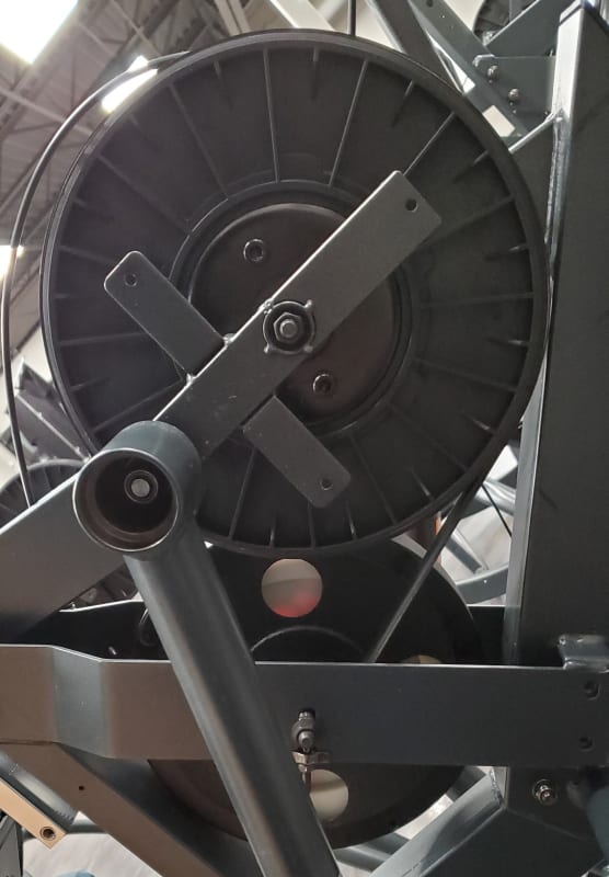
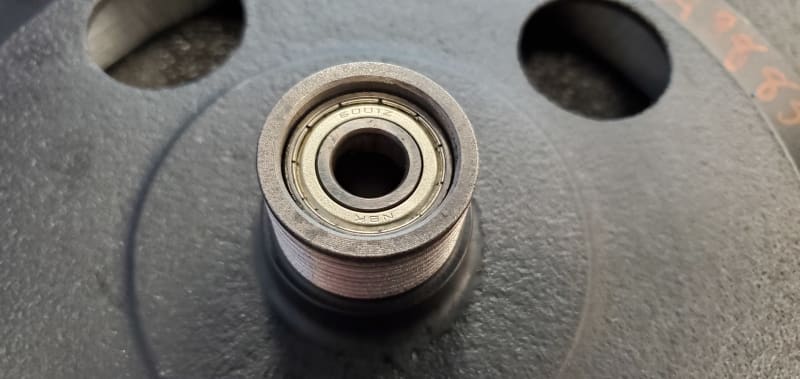
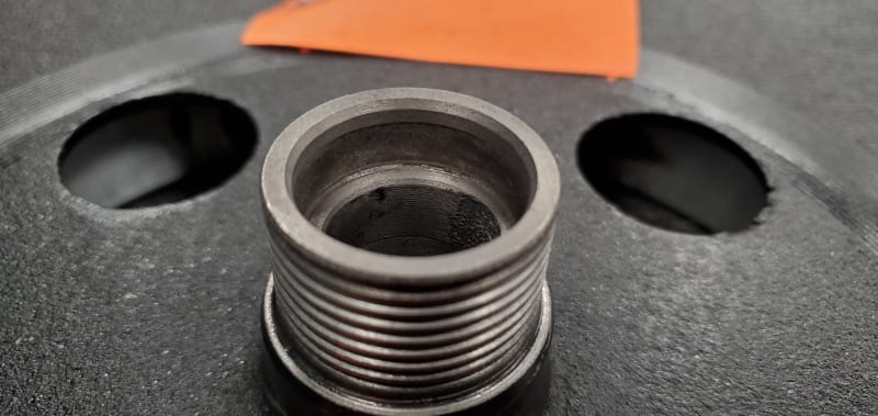
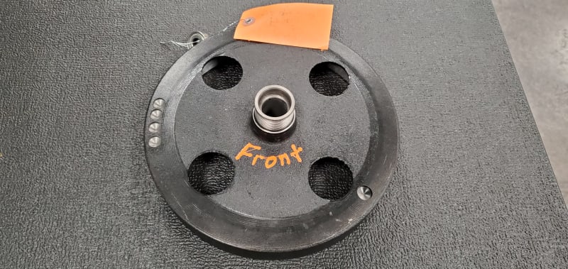
I have a line of fitness equipment that has had a small issue for some time, and now that all the bigger issues are out of the way it is time to tackle the small stuff. We have noticed that the belt side of the flywheel housing is being worn out after about a year's worth of service on a small percentage of units. The flywheel is spinning less than 500RPM. The bearings are 6001ZZ. The flywheels are cut on CNC, balanced, and inspected. Most of the radial load is coming from belt tension alone, but some comes from the eddy current resistance. This unit does not product a lot of resistance as it is a cardio piece. After the housing becomes worn the unit will make all sorts of bear rattle noises and if left unchecked, it eventually creates a thin wall condition with the belt grooves and brakes the flange lip right at the centerline of the bearing essentially locking the unit up completely. The bearings feel completely fine when removed so I do not think it stems from a bearing failure. I believe we have narrowed down the what; the bearing not initially being a tight fit even though it passed inspections. But I am still foggy as to the exact why. The exact why I think would be either the bearing bore was too loose all together (should not have passed inspection), allowing the bearing to walk slightly in the pocket. This would slowly wear away the casting. My other thought is the the surface finish is too rough in the bearing pocket, so it would be like pressing a bearing into a very fine threaded body. This would not hold the bearing well and could eventually wear the housing. The few things I can think of to help stop this from happening are; increase the wall thickness at that bearing site, increase the surface finish, add bearing loctite (similar to loctite 641) only on the outer race, and source a longer bearing so that there is more bearing surface between the bearing and flywheel.

Now to my main question. Does this sound like the correct direction or maybe someone has seen similar issues that they could shed some light on some possibilities that I have not thought of? Any incite would be much appreciated.

20211027_071939_tixgtz.jpg
20211020_073409_mdxnna.jpg
20211027_072034_qbs9fj.jpg
20211027_072026_vfkrr0.jpg
20211020_073347_edkwef.jpg
 
Replies continue below

Recommended for you

Is your flywheel spinning around a stationary shaft? In that case the bearing outside race should be interference fit in the flywheel and clearance fit on the shaft. Is this true for your case? An interference fit on the OD of the bearing should prevent any movement and wear.
 
In addition to verifying the design is correct as Tug suggested, I'd check that your process is actually producing the parts you think it is (it sounds like there are doubts). Verify your inspection procedures are adequate and actually being followed in practice. There's no point in changing the design if your process is producing non-conforming parts, you'll just end up producing slightly different non-conforming parts.

My gut says you may want to check both diameter and circularity of the bearing bore, but bearing fits are outside of my area of expertise so I could be off base there.
 
TugboatEng - Yes. The axle is stationary and the flywheel spins on it (2 of those bearings in tandem, 1 on each side). It's a running fit on the ID of the bearing/axle and press fit into the casting housing.

Stick. - I always second guess our Chinese factories at least a little. Even if they say they are doing x, y, and z it is impossible to really verify unless I fly over there. And due to Covid I have not been able to visit our factories in a year and a half and I used to go nearly every month. That said we are going to look into having the used flywheels CMM'ed for concentricity between the two bearing bores (probably will check their balance as well), but I am unsure if that will give much usable data. Most of the bore is worn away and I wonder if the small portion that is not in contact is slightly larger now from the wear and vibration during use. If we wanted to check new flywheels, that would be quite timely and costly as the failure rate for this failure mode is less than 1% and it would be like finding a needle in the haystack. I am also in the process of verifying their whole process the best I can from a distance. I would still like to do some modifications like I had discussed (or any other ideas others propose that seem viable) to help solve this. Reason being is that these machines are made to a price point and to hit the rate it becomes very timely and costly to have them machined as if they were going into a racecar.

Thank you for reply's so far Tug and Stick. Any ideas or incite helps in one way or another.
 
Is there only one bearing in the housing? If so, it's possibly oscillating or rocking due to insufficient support of moments about the bearing. Consider using two bearings in the housing or a double row ball bearing.

You could also substitute a bushing. Bushings run quieter than rolling bearings. There are a few options for low friction dry running bushings. Some extra design consideration will be necessary for the shaft in regards to wear resistance.

I do suggest using rubber sealed bearings. Your speed is low and they will hold lubricant longer in this app.
 
Tug - It already has two bearings that a few inches apart so I do not think that is the issue. I will for sure look into bushings and a rubber sealed bearing would be better in this situation as well. We went with shielded bearings because this is all contained inside a large plastic housing so the contaminate it see's is very minimal under normal operation, but rubber seals would protect the bearing better if there was a little wear. It would keep any metallic powder out. Thank you.
 
Ok, next up, the shaft. It appears to thread in to a weld nut. Is this shaft putting any axial forces on the bearing inner races or are they free to float on the shaft? If the shaft does squeeze the inner races is there a spacer sleeve between them for support?
 
Brian - I think it looks that way because the bearing wore out the bore. So yes it is not perfect anymore.

Tug - Free float with a light wave spring to keep a little positive pressure. If I hold any bearings positively in a situation like this, they always get a sleeve in between so there are no axial loads on the bearings.
 
You're making this one hard. You seem to have used good design practice.

If you're willing to use the try it and see approach, I suggest applying some retaining compound to the outer race. Loctite 609 or 635 are commonly available options.
 
Tug - Thank you we will be looking into that.

All - Thank you for all of your input and helping with this sanity check. If there are any other possibilities I am open to just about anything.
 
Is the damaged bore still round? Maybe the machines tip over once in awhile when being moved and you get a damaging blow to the bearing and housing bore.
 
Status
Not open for further replies.
Back
Top