Continue to Site

Eng-Tips is the largest engineering community on the Internet

Intelligent Work Forums for Engineering Professionals

  • Congratulations MintJulep on being selected by the Eng-Tips community for having the most helpful posts in the forums last week. Way to Go!

Foldable Fabric / Mylar in SW Assembly 2

Status
Not open for further replies.

superart

Mechanical
Jan 16, 2009
46
I am designing an umbrella for a client. I have finished the actual rigid parts of it, and it looks really neat ;-).

Now I need to put the "skin" on it. The actual product might use paper, Mylar, or fabric. Regardless of what material we decide to go with, I need to find a way to make an assembly that can have this "foldable" element to it. Thickness is not important, I tried using surfaces, but that didn't work.

I am using SW-2006 right now. If I need, I can use 2010, but I prefer to stay in 2006 if possible since that is what the client uses.

I would greatly appreciate any help anyone can offer. If solidworks doesn't have this capability, what other program would be good for this?

Thanks.
 
Replies continue below

Recommended for you

I doubt you will find an easy solution to the complex shape and doubt even more about finding a "dynamic" solution, i.e., one that changes as you open and close the mechanism. I think your best bet is Dan's suggestion of making configurations of the device in several states. Perhaps you can create a thin loft of a segment between and following the branches and pattern it.

- - -Updraft
 
I agree with Eltron and Updraft, static configurations is your best bet.

"Art without engineering is dreaming; Engineering without art is calculating."

Have you read faq731-376 to make the best use of these Forums?
 
After the configs are created, a video could be made by capturing each config in sequence. A long while ago, a macro was created to automate the process. I cannot remember it's name and cannot find it at the moment though.
 
Thinking in terms of an umbrella, could you define the edge by the tip as a 3D spline, create another one at the outer edge, then create several straight lines along the ribs as guide curves, and then do a surface or even a swept profile?
"then fold it til its all corners and go home?"

--
Hardie "Crashj" Johnson
SW 2010 SP 4.0
HP Pavillion Elite HPE
W7 Pro, Nvidia Quaddro FX580

 
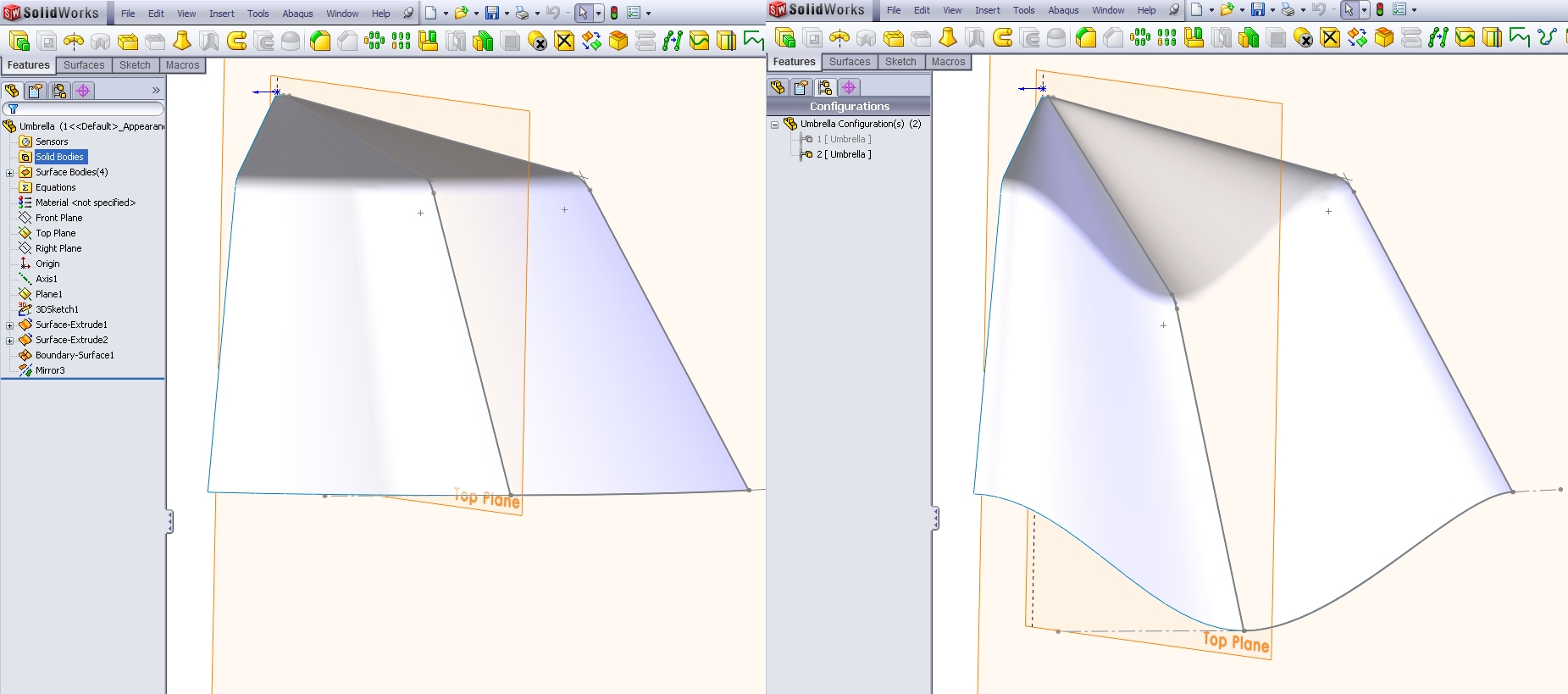
Check out the attached image and CAD model. It is basically a frame work with a boundary surface. I modify the framework in the 2 configurations. File attached from SW2010. I hope this helps.
download.aspx


Rob Stupplebeen
 
Status
Not open for further replies.

Part and Inventory Search

Sponsor