Continue to Site

Eng-Tips is the largest engineering community on the Internet

Intelligent Work Forums for Engineering Professionals

  • Congratulations IDS on being selected by the Eng-Tips community for having the most helpful posts in the forums last week. Way to Go!

Force on cylinder in flow stream

Status
Not open for further replies.

MFJewell

Mechanical
Mar 2, 2017
366
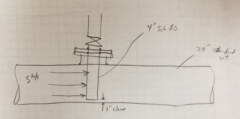
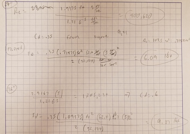
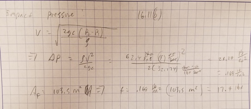
I am looking at an application that has a 4" sch 80 pipe mounted perpendicular in the flow stream of a 24" and possibly a 36" pipe. A structural engineering reviewed it and said the force on the pipe is around 20,000 lbs. I found this hard to believe so I looked at it independently. I used drag force and impact (stagnation pressure) and come up with about 23.5 lbs for the 24" application. See diagram and calculation below. Is there something I am missing here?

I believe he is just assuming a huge dP across the pipe and used that dP with the frontal area to get his value.
20170512_093905_drrrgk.jpg

20170512_093910_nuyqii.jpg

20170512_093915_xtxqrg.jpg
 
Replies continue below

Recommended for you

5 ft/sec on the sheet, right? What fluid?
What specific gravity, what coef of low (friction) at what temperature?

Is the instrument ?? suspended from "above" so there is a bending moment at the flange - What height is that flange from the pipe CL? - and no second attachment point (1 inch clear, right?)

The sketch show "dots" both at the upper side and lower side of the "flange" ?? on the opening. Two sided weld up there?

Once yo get a sideways force, and I don't know enough to calculate one yet, you need to analysze the flange, its bolts/studs and gasket (which WILL be torques and lifted up on one side, pushed don on the other) and the weld attaching the vertical flange piece to the original pipe.

Flow resistance will be calculated from the side resistance of a round object in a slipstream, factor = 1.0, unless you add some streamlining vanes on the back side.


For liquid like water for example, your calc is more or less correct. I'd be more concern about the flanged nozzle and the main run pipe wall.

You've ignored the flow blockage effects, so the fluid velocity seen by the 4" pipe will see a higher velocity....and forces.

The 20000 psi you coworker refers to, may be the nominal MAWS of the pipe.

You also have to worry a bit as you seem to be designing a sparger of some kind. If it is liquid full, then you'll see a considerable reduction in its natural frequency, and may raise concerns as regard flow-induced vibration and potential resonance especially in the 36" main run in the 5-10 ft/s range.

 
hacksaw said:
You've ignored the flow blockage effects, so the fluid velocity seen by the 4" pipe will see a higher velocity....and forces.

Wouldn't the higher velocity be seen around the side of the pipe. The stagnation point on the front of the pipe will see the highest pressures, which would relate to the highest forces. However, that is a slim section of pipe. My references materials are sitting in my office at work, but I will post a diagram of the pressure distribution if desired.


Here are a couple of clarifications:

The fluid is water @ 60 F (as seen by viscosity and density used in the calcs).

The actual velocity in the 24" and/or 36" pipe is about 3 ft/s, but we added margin. Nominal pressure in the system is under 150 psi.

This application is being designed by a coworker and an independent structural engineering consultant he hired. He asked me to check the force load after the consultant stated the 20,000 lbf on the 4" pipe. The structural engineer will peform all design necessary once the force load on the 4" pipe is verified.

The 4" pipe will be valved out during flushing of the large pipe. The 4" pipe will be used to evacuate the flushing fluid. Normally a drain would be installed on the bottom, but this is underground pipe in downtown Houston, TX and there are obstructions that prevent that on this section of pipe.

 
The drag force is proportional to the impingement/stagnation pressure certainly.

Besure to include your corrosion allowance and carry out the stress analysis for the installation. The 3 ft/s may be the design flow as you've stated. What is the line flushing proceedure and estimated flow conditions for that step.


The 3 ft/sec is the flushing flow rate. After the pipe has been flushed and the fluid evacuated, the 4" pipe will be removed and the top entry connection will have a blind flange installed.
 
Status
Not open for further replies.

Part and Inventory Search

Sponsor