Continue to Site

Eng-Tips is the largest engineering community on the Internet

Intelligent Work Forums for Engineering Professionals

  • Congratulations The Obturator on being selected by the Eng-Tips community for having the most helpful posts in the forums last week. Way to Go!

Force Required to Crush a Tube

MECHENGTOM

Mechanical
Jan 22, 2025
5
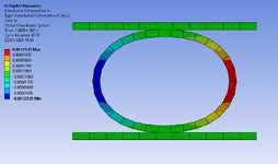
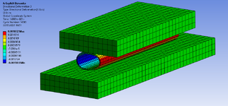
I'm looking for ways in which I can calculate the displacement (vertical and horizontal) of a tube being crushed between two flat plates. I have managed to set up a non-linear material profile and simulate this problem using ANSYS however would like some sort of hand calculation to ensure I am in the correct ballpark. Length of the tube is 0.1 m and a force of 5 kN is applied to the top plate (tube dims and properties as illustrated in the excel spreadsheet image).

I have stumbled across Roark's Formula for Stress and Strain using Table 9.2 Formulas for circular rings however my calculated values are significantly less than my FEA - not sure where I'm going wrong here - Am I missing something to be so far out?
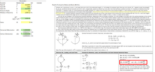
Roarks Formula for Circular Rings.PNG

Tube Crush Sim.PNG
 
Last edited:
Replies continue below

Recommended for you

Thanks for the reply! however even when applying relatively low forces on the simulation (to the extent where the deformation is mainly elastic) the values still do not align. Am I missing something?
 
Roark is a linear analysis assuming small displacements. your FEM is large displacements, geometric and maybe material nonlinearity.
 
In regular beam design, you assume that the flanges of the beam can expand or contract laterally, so there is no lateral load in the flanges.
If you bend a wide flat bar in the weaker direction, the top and bottom surfaces are connected together, and can't expand laterally, which changes the strain in the direction of bending. If I recall, this is a difference of (1-nu^2) so roughly 10%.
In your case, if the formulas are for a circular ring, and you apply them to a pipe, I would assume you get the same effect.
Roark addresses the wide-beam issue somewhere, I don't know if he makes that distinction on the circular-ring formulas.
But whatever the difference, some of it might be due to that effect.
 
I dare say you'll get more traction if you post the deflection vs force FEA result. Even in the elastic region a ring will give a softening stiffness curve.
 
Last edited:
Thanks Littleinch, I'll take a look

SWComposites, yes I understand - Maybe if I try with much smaller loads, the displacements may align. I'll take a look

JStephen, Thanks for that reply - I'll take a look into the wide beam theory, maybe that will help me out.

r6155, I am planning on testing a range of tube dims to verify my model however will not be for a couple months. Was just curious to see if I could calculate the displacement.

GregLocock, I'll get back to you on this one, thanks.
 
A few thoughts:

Your FEA shows a diameter change of 3.4mm horizontally (I'm assuming that's the X direction), which is large in relation to the wall thickness of 1mm, so I wouldn't expect it to line up with Roark's anyways (as others have already stated). Also, having the displacement be asymmetrical just strikes me as a bit odd.

I quickly duplicated your hand calcs and got 0.15 mm Dh and -0.17 mm Dv, so you might want to double check your calcs (I might be wrong since it was quick). For reference, my calcs had R = 7.438mm. I believe the long ring assumption you highlighted would require converting your load W to load per unit axial length, so 50 Kn/m.

Also, is that an acceptably fine mesh for this type of analysis? I've never done any FEA with material non-linearities or used Explicit Dynamics, but if this was a static analysis, I'd be looking at increasing the mesh density through the pipe wall thickness before I trusted the results.
 
Hi Stick,

Thanks for the reply!

Fairly a newbie to non-linear FEA analysis myself, However thanks for pointing out the force per unit length- missed that one. that certainly brings me a bit closer.

I think the asymmetrical displacements were due to my poor meshing skills - I have since updated the model and it deforms a lot more how I would expect.

Comparing this to my calculation in line with Roark's, I'm approximately out by double - I imagine this can be explained by Roark's being a linear model of calculation hence not considering the plastic range.

TUBE CRUSH 2 @ 10kN.PNG
 
The KISS rule is 3 or 4 mesh elements across a wall thickness. Your mesh is horribly coarse, unless that's just ANSYS displays it.

EDIT: I'm usually running garbage Solidworks Simulation, but I'm not sure that Explicit Dynamic is the best simulation type for this scenario. ANSYS describes it as more suited for transient events, temporally bounded. I have no idea what that would be adding to the calculations, but in this case I would be running a simple static load deflection study first. If that didn't make sense, then I would re-run it as non-linear/larger displacement study. Even ANSYS says if you aren't specifically interested in time-dependent effects... don't run an explicit dynamic study. Use an implicit dynamic study. https://www.ansys.com/blog/what-is-explicit-dynamics. Unless you want to crush the pipe entirely, I would see this as a basic "barely non-linear" study. Particularly if you're comparing to hand calcs, which are fully elastic.
 
Last edited:
You can do an upper bound hand calc solution by assuming (say 6) fully plastic hinges form in the metal.
 
The KISS rule is 3 or 4 mesh elements across a wall thickness. Your mesh is horribly coarse, unless that's just ANSYS displays it.

EDIT: I'm usually running garbage Solidworks Simulation, but I'm not sure that Explicit Dynamic is the best simulation type for this scenario. ANSYS describes it as more suited for transient events, temporally bounded. I have no idea what that would be adding to the calculations, but in this case I would be running a simple static load deflection study first. If that didn't make sense, then I would re-run it as non-linear/larger displacement study. Even ANSYS says if you aren't specifically interested in time-dependent effects... don't run an explicit dynamic study. Use an implicit dynamic study. https://www.ansys.com/blog/what-is-explicit-dynamics. Unless you want to crush the pipe entirely, I would see this as a basic "barely non-linear" study. Particularly if you're comparing to hand calcs, which are fully elastic.
Thanks for the feedback, never heard of the kiss rule - I'll look into that.

I did initially try a static loading scenario however didn't give me what I was looking for. The implicit dynamics route sounds good to me - I'll give that a try thanks.
 
The factor of 2 is just because Roark's is calculating change in diameter, while your Ansys result is effectively change in radius (if you just look at the max displacement). But they also differ by an additional factor of about 100. Your Ansys plot shows a diameter change of 2.5mm (range of your deformation scale), while your hand calc shows 0.027mm. I would reduce the loading in Ansys until your deflections are smaller (say a diameter change of under 0.25mm) and then rerun your hand calc with that loading to check agreement (also double check your hand calc is done correctly). That should reduce the effects of large displacements and/or plasticity (hopefully). Also, you should refine the mesh until you get more elements through the thickness of the pipe. I'd concur with Orange_kun that 3-4 elements is probably a decent target, but since this sounds like a learning experience for you anyways, keep pushing the mesh finer and see when the change in results slows down with each mesh refinement.

Also, KISS = Keep It Simple, Stupid
 
Just an observation to think about.

When looking at the displacement of the tube with gradual load application, I would think that as the load is initially applied, it can be considered as a point load and can be modeled using the Roark's formula method (modified for Poisson's effect). Due to symmetry, 1/4 of the tube can be modeled, taking 1/2 of the applied load. The free edges of the 1/4 tube length will be fixed in rotation (vertical and horizontal tube ends free in translation). As the load progressively increases, the applied contact load will start to move, the centroid of which will move away from the vertical C/L. The idea is that as the tube starts to deform under the increasing applied load, the contact point / distributed length will start to change in shape.

Obviously FEA will capture this change in load application. If a hand analysis is to be used, I would incorporate the ability to change the position of the contact point(s), defined by the zero gradient location. Hope this observation helps.
 
Last edited:

Part and Inventory Search

Sponsor