Continue to Site

Eng-Tips is the largest engineering community on the Internet

Intelligent Work Forums for Engineering Professionals

  • Congratulations SSS148 on being selected by the Eng-Tips community for having the most helpful posts in the forums last week. Way to Go!

Foundation Repair Bracket - Helical and Resistance Piles

Status
Not open for further replies.

RFreund

Structural
Aug 14, 2010
1,885
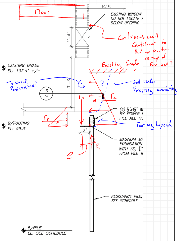
I am curious about the following situation that I assumed was fairly typical. See Attached Sketch.

An exisitng structure with a strip footing and partial basement (or full basement I suppose) requires underpinnig. A foundation repair bracket with helical or resistance pile is used. According to IBC the pile is laterally unbraced, as far as I can tell it does not meet the requirements of 1810.2.2 (2015 IBC). If the pile is embeded in firm soils (N>4) then the pile is assumed to be braced at a point 5' below grade. If there are soft soils N<=4 but greater than 0, then the pile is considered braced at a depth of 10'.
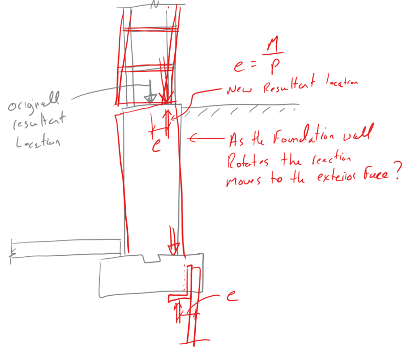
The ICC-AC358 (acceptance critiera) tests pile repair brackets with the pile shaft unbraced for a length of 5'. Therefore if you have pile/bracket combo that is tested in accordance with the ICC AC358 guidlines, the allowable axial load already considers the moment caused by the eccentricity. However, it would not include the moment due to the lateral earth pressure. How is this situation justified then? A few thoughts:

1. If the foundation was stable before and the bracket/shaft can handle the moment due to the eccentricity, then all is "fine".
2. Check the bracket / shaft for the additonal moment due to lateral earth pressure. Apply the moment to the shaft from the eccentricity and lateral earth pressure. Check the shaft as 5'-0" or 10'-0" unbraced with an appropriate K factor at each end (maybe 0.8?). Check combineded axial and bending.

If you have a shaft in soft soils it seems you have no option but to go with the second case. And it seems like the second case doesn't come close to working. Some additional components offering resistance to the moment created by the eccentricity and the lateral soils pressure:

[ol 1]
[li]The moment strength of the pile.[/li]
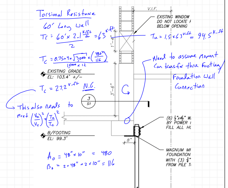
[li]Torsion strength of the foundation[/li]
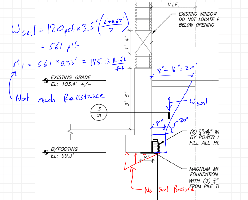
[li]Soil on the exterior side of the footing.[/li]
[li]Passive pressure[/li]
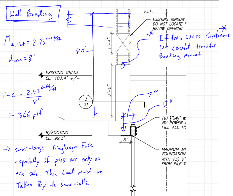
[li]The masonry wall cantilevering down form the floor above.[/li]
[li][/li]
[li][/li]
[/ol]

Sketch


Underpin_Repair_Bracket_-_Helical_or_Resistance_Pier_gwslit.png


EIT
 
Replies continue below

Recommended for you

It seems to me that unless the wall is very weak, the eccentricity (e) for the pile is only the distance from the edge of the slab to the centerline of the piles.

As far as the lateral earth pressure diffential, isn't it balanced by pressure on the opposite side of the basement?
 
Draw a total stress diagram for the wall from floor to footing for both bending and compression. My bet it will show the resultant of that combination will not leave the kern. In other words it works.

edit: Of course average it for the length of the wall.
 
Can you transfer the moment from the bracket to the footing, so the screwpile can be 'axially' loaded?

Dik
 
RFreund,
It appears that there is a concrete portion of the wall below (3'-6") and then masonry above. Is that correct?
And is the masonry wall reinforced in any amount? ...and tied into the concrete wall below with rebar?

If not, then the wall is unstable to begin with never mind the piling. It would be behaving as a cantilever retaining wall below with not enough spread footing to cantilever properly.

But back to your question - if there's no continuity of bending strength in the wall between footing and floor above, then yes, you've got an issue with resolving the eccentricity of the pile vs. the eccentricity of the earth pressure on the wall.

If there is a fully flexure-resistant wall from footing to floor then perhaps the eccentricity is taken out by the wall (the wall is a vertical beam-column with axial load and an applied moment at the bottom)

Unless you check the magnitudes vs. kern (per oldestguy) the only thing I see resisting the moment might be multiple bolts in the bracket itself forming a force couple on the footing (i.e. the bracket and footing are one and create a resistance to rotation at the top of the pile. But even with that would the pile be able to resist the bending along with the required axial together?


Check out Eng-Tips Forum's Policies here:
faq731-376
 
Thanks for the responses. I would like to expand on some of these, as I have given them some thought but I don't think the "calc out".
Let's add some numbers to this.
Wall load: 5kip/ft
Wall length: 60'.
Foundation wall height: 4'
Footing thickness: 1'
Basement height 8'.
Grade is 4.5' above the top of footing.
3" pile

HotRod said:
It seems to me that unless the wall is very weak, the eccentricity (e) for the pile is only the distance from the edge of the slab to the centerline of the piles.

So this would suggest that the foundation wall handles the eccentric moment. There are a few ways it could do this:
1. Torsion - for a long stretch of wall, say 60', this Torsion would be rather large.
Torsional_Resistance_jfx0lw.png


2. Bending and a T/C couple between the slab on grade and the first floor. This would not work in this case as there could be a hinge at the top of the foundation wall.
Wall_Bending_xz7iae.png


3. Dead weight of the soils on the back side of the footing.
Soil_Resistance_uxlu5z.png


Sketches

Oldest Guy said:
Draw a total stress diagram for the wall from floor to footing for both bending and compression. My bet it will show the resultant of that combination will not leave the kern. In other words it works.
I beleive it has to leave the kern. We can no longer rely on soil pressure below the footing as it is now being supported by a deep foundation. The only reaction point is at the edge of the foundation wall + the pipe dimeter. So there are two general systems to restrain this rotation. The first is the foundation wall (described above). The second is the bracket and pile. The more I think about it this becomes a stiffness problem, but I'm willing to ignore that for now.

Dik said:
Can you transfer the moment from the bracket to the footing, so the screwpile can be 'axially' loaded?
Yes that is possible. But how do I show the footing can resist this moment?


EIT
 
Depends on the magnitude of the moment... maybe it can be resisted as plain unreinforced concrete.

Dik
 
You missed something about systems that resist rotation. How's about that floor load? As the wall top end tends to rotate out from under that load, the center of pressure moves to the inside edge. Also the earth pressure likely redivides or even becomes zero. Historically have any of these repair methods caused a wall failure? My memory says none. We also usually have a resistance to failure in the wall due to the restrictions at the corners.
 
Oldestguy said:
Historically have any of these repair methods caused a wall failure? My memory says none.
I agree, which is why I'm struggling with this. My calcs seem to indicate that this really isn't close to working. But, I'm likely missing something (as you have indicated, but more on that below).

Oldestguy said:
We also usually have a resistance to failure in the wall due to the restrictions at the corners.
Failure in the corners would actually agree with my calculations. Meaning the eccentricity causes a torque on the concrete foundation wall where the critical section is at the corner.

Oldesguy said:
You missed something about systems that resist rotation. How's about that floor load? As the wall top end tends to rotate out from under that load, the center of pressure moves to the inside edge. Also the earth pressure likely redivides or even becomes zero.
I'm trying to understand this a bit better. I can see this being a good argument for why the eccentricity should only be taken from the edge of the concrete, but I can't quite seem to draw this free body force diagram. Here is an attempt:
Resultant_Location_bchz6u.png


EIT
 
It's a complicated issue. The wall has restrictions in two directions, vertical as well as horizontal, and tension capabilities, in spite of some cracks. It takes a very long wall, not usually found n houses, to limit the discussion to vertical forces, etc. Putting these issues to calculations runs into the changes that take place with even small movements. Sometimes a scale model helps to resolve or explain what is going on. Then comes changes in how loads are applied to the wall and at what values.
 
I have recommended, designed and made after-construction inspections of a lot of these, mostly for residential repair.
About 1/2 of the time, I promote installing these on the inside of the building. There have been a couple of instances where placement on the inside was required, due to the simple statics of the situation. I could also see an advantage to alternating the piers from inside to outside, in some questionable situations.
 
Status
Not open for further replies.

Part and Inventory Search

Sponsor