Continue to Site

Eng-Tips is the largest engineering community on the Internet

Intelligent Work Forums for Engineering Professionals

  • Congratulations KootK on being selected by the Eng-Tips community for having the most helpful posts in the forums last week. Way to Go!

Foundation slab for a steel tank - joints

Status
Not open for further replies.

Andrew88

Civil/Environmental
Aug 7, 2017
42
Hi all,

I want to design a reinforced concrete base for an open top steel tank. The tank has a diameter of 25m and height of 2.9m. I am thinking about the base that is 150mm thick, thicker around the circumference. Most of the time the tank will be empty.

The maximum pressure that will be exerted on the ground will be not more than 40 kPa and moments in X and Y directions shouldn't exceed 10kNm/m. To simplify reinforcement installation I want to go with a standard mesh A393 at the top and bottom face and circumferential/radial reinforcement in the proximity of the circumference of this slab.

As you can see I get reinforcement density in the slab of 2x393/(150x1000)=0.524%. The concrete will be poured in temperature of 10 Celsius degrees and I don't expect it to heat in the summer to more than 40 Celsius.

Here I would be grateful if you can answer my questions:
1. What is the best pouring schedule here? I though about dividing the circle into heactagonal and pouring 4 in one day and 4 on the next.
1. What is the best way to create gradient on the floor as I need a liquid to drain towards specific location? Would it be benching?
2. Would you use contraction joints here? If yes, at what spacing?
3. Would you use expansion joints? The linear expansion seems to be about 1cm if I take t0=10 and tfinal 40.

Thank a lot,
Jed
 
Replies continue below

Recommended for you

Is this slab also the tank bottom, or is there a steel bottom on top of the slab?
Is this to comply with any particular code?
 
Yes. Slab is the bottom of the tank. Tank itself will be bolted down to the base along its circumference.

Would be better with a code to have some guarantee it is not going to crack and leak as crude sewege will be stored there but pleae say what is on your mind.

 
My preference would be to cast the whole thing at one time, without jointing. Your quantity of crack control reinforcement is about right, but I would use bars rather than mesh, and only one layer, centrally located.
 
For liquid containing structures, especially wastewater/sewage structures, I'd distribute the T&S reinforcement equally to each face rather than place in the middle thickness. If you're under ACI 350 or similar this is required.

Otherwise I agree with hokie that you reinforcement percentage seems appropriate for a liquid containing structure. It's also worth noting that whatever rebar/mesh you use; tighter spacing of smaller bars is preferred over wider spacing of larger bars for crack control.

Ian Riley, PE, SE
Professional Engineer (ME, NH, VT, CT, MA, FL) Structural Engineer (IL, HI)
American Concrete Industries
 
The tank to slab detail is critical and has a lot of things happening at it for this type of installation.

6 inches for a slab like this feels incredibly thin. It kind of comes down to interaction with the subgrade, but your slab needs to be strong enough to ensure that you don't have detrimental cracking from deflections caused by the differential settlement of the subgrade. Also, trying to squeeze two layers of steel in a situation where you will likely need at least two inches of cover on the top and three inches on the bottom isn't realistic.

I would start by reading ACI 350, at a minimum, and looking through a large number of other references that are out there.

 
TME,
His slab is only 150 thick. Good luck with getting two layers to work in that. Not familiar with ACI350, but a central layer of direct tension reinforcement will control cracks.
 
Hokie, I missed the thickness was that thin; thanks. You're right, that does make it impractical to have two layers. I've fit 2 layers into that thickness before but always with complaints from the contractor.

I'll have to check ACI 350's language but I know other similar codes specify that if you're below a certain thickness you can use single layers of reinforcement on the flexural tension side (or whatever side is likely to crack).

TLHS, I agree, that does sound too thin. I would expect 200 mm at a minimum (and 2 layers of reinforcement does fit in 200 mm).

Ian Riley, PE, SE
Professional Engineer (ME, NH, VT, CT, MA, FL) Structural Engineer (IL, HI)
American Concrete Industries
 
I think some of the precast tank erectors use very thin floor slabs, 4" or so, but I don't have any details, and don't necessarily recommend that. And I assume that would also be dependent on having proper subgrade below it. And that's for potable water storage, where leakage is undesirable, but not an environmental issue, either.

For the attachment from the tank to the slab, I would recommend using a detail that has proven successful on prior projects in the area. What I've usually seen is some form of embedded channel with a weld connection to the shell. You could use something that looks good on paper only to find it leaks like a sieve, and fixing it may not be that easy. If bolting to the slab, you may have nominal design loads on the bolts that are very low or even zero, but may develop very high bolt loads due to differential settlement, etc., so make sure the bolts are not the weak point in the detail.
 
Thank you all for replies.

Yes, it seems like 150mm will be really to thin for 2 layers. I will increase it to 200mm - 8 inches.

The detail of the connection between tank and slab is attached. It is standard detail from Permastore so I don't think there will be issues with it.

The foundation was modelled as elastic with Winkler model where modulus of subgrade reaction is 7700 kN/m3. For this I receive bending moments that are close to 0 at the upper face of foundation and about 10 kNm/m at bottom face. I am a bit concerned with differential settlement, so would use both top and bottom reinforcement regardless of moments.

Now to get the ratio of steel of about 0.5% I need 1000mm2 of mesh in the 1000x200mm section. I can do it with 8mm bars at 100 centers. This also should help to limit cracks.

Could you advise on my questions regarding joints in this slab, please? If I assume that my assembly temperature is 10C degrees and the temperature gradient between top and bottom 30C degrees (max. 40, min 10, I think this situation might realistically occur in UK, open and empty tank in summer) then my moments go up to above 30 kNm/m and reinforcement would need to be increased significantly.

I need to divide the pour into 2 days at least due to construction reasons.

 
 https://files.engineering.com/getfile.aspx?folder=711864f3-c738-494e-8f78-6ec7d594eefa&file=Flat_Base_Foundation_DetailMK.006F.pdf
jedrzej88 said:
...please say what is on your mind.

Here is a "reality check"... this is the most "troubled" cast-in-place, slab-on-grade design that I have ever come across.

The slab is 200mm thick.
Bottom rebar mat cover is 75mm.
What is top mat rebar cover, 50mm? For raw sewage, using plain (not epoxy coated) rebar, cover should be more like 75mm:

Wastewater_Slab-1_vepzpt.png


8mm rebar, thin as a wood pencil, is like wet spaghetti noodles in the lengths needed for this project. Labor costs to support / place / tie a very large number of small bars will be very high.

Consider that workers will be walking on the "tiny" rebar mats during concrete placement... down go the mats, bent and pushed to the bottom of slab.

The design "saves concrete", "costs a fortune" for rebar placement, and the "as-built" condition is unlikely be anywhere close to the (flawed) design.

There is plenty more, but I'll stop there unless you want to continue with suggestions on what to do about it.

[idea]
 
SlideRuleEra, thank you very much for constructive comments and yes please continue with suggestions.


Jedrze88 said:
What is the best way to create gradient on the floor as I need a liquid to drain towards specific location?

This needs to be addressed before deciding on the rebar pattern. For example, if the drain in at the center a radial rebar pattern will likely be best.
If the drain is at the edge, there are a more options.
Also, the slope of the floor; is it minimal (say 1%) to shed liquid, or several percent to allow solids to be collected at a center drain using a rotating "rake"?

For the slab, you have expressed concern about differential settlement. If proper attention (and money) are directed to soil preparation that potential problem should be minimized, because:
1) The soil loading is relatively light.
2) Soil loading is fairly uniform (weight of the tanks at the perimeter, but primarily the contents of the tank).
3) If there is differential settlement, there may be much bigger problems... the slab could crack, leak, and over time, destroy the slab/rebar with corrosion.

If differential settlement "goes away" as a potential problem, design of a cost effective slab becomes much simpler. Tell us about the shape of the tank bottom, that will determine the direction for slab/rebar suggestions.

[idea]
 
A small sump would be installed at the edge and gradient of about 1% is suitable.

I am waiting for the geotechnical report but hope to have a decent layer of chalk at low depth and a uniform strata.


jedrze88 said:
A small sump would be installed at the edge and gradient of about 1% is suitable.

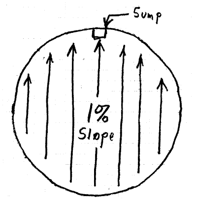
Good, that make everything much easier. For one of our cooling tower basins (80+ meter diameter) I had the design team slope the entire floor, see the sketch. (Slope is to help plant operations wash down & remove sediment during outages when the basin is drained.) The floor slopes in one direction so that it remains flat & the rebar profile does not change, but not level. At first, the design team though this was a "joke"... it was not, alternate proposed schemes were more difficult (and expensive) to build watertight. The sloped flat bottom concept works so well, that 10 years later we did two more basin floors the same way. Suggest considering a similar concept for this project:

BasinSlope-1_zzetyn.png


A varying height reinforced concrete perimeter wall will be needed to keep the tank/anchor bolts level.

IMHO, if differential settlement can be dismissed, one rebar mat should be sufficient. Problem with two mats is that much thicker concrete is needed to get meaningful mat separation AND half the rebar (bottom mat) is in the wrong place (near the bottom) to provide essentially continuous reinforcement.

Suggest considering the following:

Initial slab thickness assumption, the proposed 200mm.

One rebar mat, 0.5% to 0.6% reinforcing steel ratio (each way).

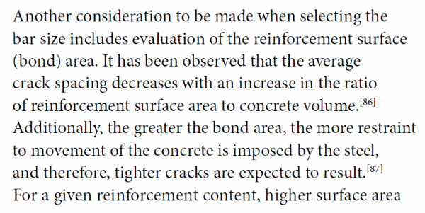
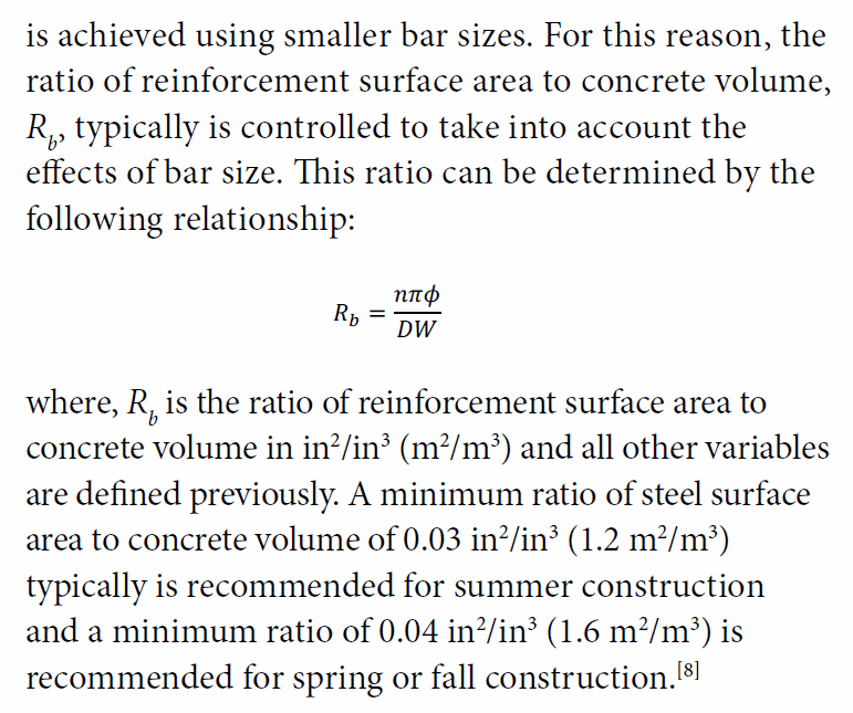
Rebar size, a compromise of "large" rebar for structural strength during concrete placement with rebar spacing adequate to prevent honeycombing, and "small" rebar selected so that the reinforcing steel ratio of rebar surface area : concrete volume is 1.2 m[sup]2[/sup]/m[sup]3[/sup] to 1.6 m[sup]2[/sup]/m[sup]3[/sup] (This is to ensure that the rebar/concrete bond area is adequate to be effective as continuous reinforcement).

Mat concrete cover on the top is a nominal 75mm.

Mat cover on the bottom is what ever remains after thickness of the two-way rebar mat is accounted for. (Should be > 75mm, otherwise, increase slab thickness to make this happen.)
Note: Do not make the slab "thinner" because bottom mat rebar cover is > 75mm. The rebar needs to be "high" in the slab for best performance as continuous reinforcement.

[idea]
 
Thanks again!

I know that we can't pour it in one go so I will provide continuous reinforcement through construction joints.

If I understand properly the slab will be on one end about 200mm+ 0.01*25m = 45cm thick whereas on the end with a sump 200mm. The reinforcement ration will drop sginificantly on the thick side but I guess this is alright?

To obtain reinforcement ration each was of at least 0.5% I will consider 12mm @100 centres. For a 200mm thick slab it will give me about 0.57% each way.

Where does this values of 1.2-1.6 m2/m3 come from? Would you be able to give me some reference to it, please?
Let's say my 12mm mesh @100mm c/c yields 12*pi = 0.038m2/1m of bar. I will consider that 1m3 of concrete occupies 5m2 of slab with 200mm thickness. For this I get the ratio of 0.038*10*5*2 = 3.8m2/m3 o which is way more then recommended. Unless the range 1.2-1.6m2/m3 is only for one way? How can I take it down keeping reinforcement ratio at about 0.5-0.6%?


jedrze88 said:
If I understand properly the slab will be on one end about 200mm+ 0.01*25m = 45cm thick whereas on the end with a sump 200mm.

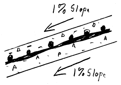
No. Slab thickness is constant. Top of subgrade slopes 1%. Bottom of slab slopes 1%. Top of slab slopes 1%.

BasinSlopeBottom-1_mv0gda.png


jedrze88 said:
I will consider 12mm @100 centres.

Too small and too close together. I get a a surface:volume ratio of over 18 m[sup]2[/sup]/m[sup]3[/sup] for 12mm @ 100 mm.
See my 18 Jan 2019 post about "small", "closely spaced" rebar.

jedrze88 said:
Where does this values of 1.2-1.6 m2/m3 come from?

SurfaceRatio1-1_qf2nsh.png

SurfaceRatio2-1_ivjjoa.png


"Continuous Reinforced Concrete Pavement Manual", pages 36 and 37

[idea]
 
Just a point:-

All other things being equal, slab thickness, concrete strength, etc:-

Having 12 diameter bars at 100 ctrs vs having 16 diameter bars at 200 ctrs, noting roughly the same reinforcement content. The 12's at 100 ctrs will result in better crack widths between the bars which would be more desirable given the contents and the fact that you won't want it to leak.


Some other food for thought:-
I would consider the 200 thick slab being proposed with a single layer of reinforcement to be far too thin (flexible) for me to be comfortable with it, unless it was sitting directly on rock or similar. You want the foundation for your tank to be stiff enough to not be too affected by any differential settlement, though this might be mitigated to some degree by over excavating and compacting hard-fill to form a stiffer gravel raft under the slab. Something like 300+ thickness with 2 layers of reinforcement sounds more comfortable to me, last thing you want is to be chasing repairs to leaks, the risk of downtime from the operator might dictate a closer look at the risk/reward in going thinner with less reinforcement based on volume or surface area.

200 is also potentially limiting in fixing down the perimeter of the tank, especially if there is only a central layer of reinforcement 100mm down with shallow fixings only into the cover concrete. If you have a perimeter edge thickening you are also introducing a potential point of restrain for the shrinkage if you want more concrete to fix into around the perimeter, so keep that in mind.

Note depending on how the tank is fixed you also potentially have a horizontal thrust at the base of the wall around the perimeter than needs to be resisted by your reinforcement in addition to any moment, probably depends on the relative stiffness of the tank wall vs the base and how the hoop stress is distributed through loading and temperature cycles after its locked in place by being bolted down.

You noted that the tank might be filled/emptied on a regular basis, you should look into the durability of the concrete itself, a varying cycle of wetting and drying can greatly decrease the durability of the concrete in the presence of waste water (microbial attack I believe which is worst at the 'tide line' due to wetting and drying effects). Certainly this can be mitigated through careful consideration of the mix design or via coatings applied to the concrete.

Lastly appropriate curing of the concrete should be adhered to for best long term performance.

I agree with pouring it as one piece, but with the addition of appropriate waterbars/waterstops at any joints you could certainly split it up into smaller pours. Its no different to any other water retaining or tanked structure in that respect.

With the sloped base being proposed, I'd probably create a constant elevation concrete nib or upstand around the perimeter to support the tank, this avoids having to fabricate the tank with varying wall heights around the perimeter.

 
Thanks. I had a read and a 16mm bars at 180mm c/c seem reasonable.

Did you use any joints in this CRCP approach in any of the projects you mentioned?
 
jedrze88 - Yes, many joints. For our project, the basin serves as the foundation for the cooling tower, which is very heavy and includes operating equipment. Because of the large diameter, poor soil, high wind requirement, high seismic requirement, and project use (Occupancy Category IV, for a base load electrical generating station) the foundation is much thicker and heavily built that what you have described for your project.

For your project, consider preparing drawings that do not show any joints. However, include a detail for typical joint construction AND a note giving a Contractor the option of proposing joint locations for review/acceptance by the Engineer. As hokie66 mentioned, best if there are no joints and it may be reasonable to construct a slab of this size without joints. The Contractor's option approach keeps you out of a Contractor's "means and methods", yet allows the Engineer to control the design. We used this type option many times... some Contractors are more capable / resourceful than may be expected and can come up with surprising solutions... that work and are cost saving.

[idea]
 
Status
Not open for further replies.

Part and Inventory Search

Sponsor