Eng-Tips is the largest engineering community on the Internet

Intelligent Work Forums for Engineering Professionals

Friction coefficient for steel-steel conical clucth

Status
Not open for further replies.

claudiodeviaje

Mechanical
Jun 19, 2005
45
0
0
DE
Good morning everyone!

I'm designing a conical clucth for a simple gear transmition. The cup and cone are made of steel (type yet to define).

According to my textbooks the static friction coefficient for steel-steel (dry) is something between 0.45 and 0.8 depending on the surface finishing. The problem is that they don't specify which surface finish are meant.

Could you please point me where I could find the coeficient for the different surface finishings?

Thank you,

Claudio
 
Replies continue below

Recommended for you

You will not be happy with the performance of a steel on steel clutch. It will gall, snag, stick, slip, and overheat.

Make one of the elements out of something dissimilar. One traditional choice is cast iron.


Mike Halloran
Pembroke Pines, FL, USA
 
Thank you Mike for your prompt answer!

What I'm planning to build is this:
Gear_axle.jpg
(still in sketch stage)

The coupling will be allways done in stop position (no rotation). After coupling the axle will rotate (1 or 2 complete rotations). After a complete stop, it will disengage.

Which material combination could you recomend for such an application? Still cast iron and Steel?

Thank you for your help!

Claudio
 
Relying on a dry friction of steel on steel is always going to be iffy. Rust, dirt, a smidge of grease, water or just about anything will see your coeffcient of friction drop to the typical value of 0.3, or typical lubricated value of 0.15.

Having said that if you can guarantee that no sliding will take place, and a friction coefficient of 0.15 is adequate, then your proposed design should be OK.

But, if it ever slips in use, or engages or disengages while rotating, you will be in the world of hurt as described by Mike.

Incidentally it looks like you are using keys to transmit torque in a sliding joint. Very ugly.


Cheers

Greg Locock

Please see FAQ731-376 for tips on how to make the best use of Eng-Tips.
 
The whole system is designed to allow engage and disengage only when not rotating. The clutch is going to be inside a housing, but still could spilled with oil. Probably 0,15 will do, but I have to look closely.

About the keys...
The Axle is about 300mm long and moves downwards. The Cone and cup will stay in the housing as the axle slides donwards (Cone disengages from cup, und axle disengages from cone). After that the axle moves up, engages the cone which engages the cup(guides line up the cone and axle). The 3 keys are DIN 6885 type E, which are supposed to be for sliding applications. They were chosen because of lack of space and the transmitted torque will be very low.

What other torque transmition would you recomend instead?

and bach to the original question.... How does the surface finishing on the cluth influences the friction coefficient

Cheers,
Claudio
 
A couple of thrust bearings are going to have to be working full time to keep your clutch engaged. All my vehicles' clutches are set to clamp internally, so the thrust bearing only has to work during dis-engagement.

If its really only has to be engaged every now and then while stopped, then these commercial parts can be arranged to form a dog clutch by slidng the outer sleeve.

Could you slide your gear on a splined shaft or slide the entire shaft axially through plain bearings?
 
As I said before, the clutch will be used every now an then, and will engage ONLY in stoped position. Very low torque will be transmitted and while engaged, the axle will do maximum 1 rotation, not more.

The dog clutch doesnt really work for this application. The gears can't move before and during engagement. Thats why the cones are perfect. One other isue is that the clutch has to be as compact as possible...

The axle will slide through the gears (which are fixed to the housing and mounted on sliding bearings). When "pulled" the clutch will engage, when "pushed" the end of the axle will come out of the housing.

The axle will be mounted on its own housing with 2 Ball bearing "B". This compete housing will move back and forth. The sliding bearing is in the gears housing and will prevent that the axle bends.

Clutch Sliding
_ ___ bearing Bearings
| \ \ |
| \ \ | _________ B B
--------------------------------------
--------------------------------------
| / / | ------------ B B
|_/ /__| fixed <------>


I was thinking of going with an O-Disposition for the thrust bearing. What do you think about it?

Cheers!

C
 
And going back to the original question...

How does the surface finishing influences the friction coeficient?

The coeficient in textbook are normally given for "normal" surfaces or extra-super-duper-polished ones?

And the last one @Greg... The clutch will probably get spilled with oil, but will not be soaked in it. When you sugest 0,15 for lubricated slutch, does this means soaked in oil of just spilled with oil?

Acording to my calculation, if I use a 0,3 as friction coeficient, the angle of the cone is ca. 17°. With 0,15 I'll need ca. 9°. Supposing I have no retraction force...

Thanks again!
c
 
"Make one of the elements out of something dissimilar" - I agree with Mike. You run into galling etc. when using similar materials. One problem I see with metal surfaces is that any wear debris will go right into your bearing unless you run a seal on the inside also.

If you have your heart set on the cone set-up err on the large size, you can always remove mating material from the cone if necessary.

If you want a tight package I would consider a friction disc acting perpendicular to the shaft axis. Your activation distance is relatively small, you have a wide choice of friction materials, you already have a flat surface on the gear, and you can use a variety of different means to achieve the sliding joint (keyways, splines, square, hex, etc.).

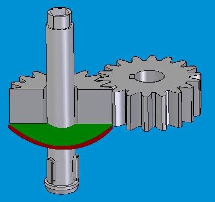
gear.jpg

Excuse my poor drawing, but the green plate is the friction material and the red plate interfaces with the shaft. The friction material can be fixed to the red plate or splined and allowed to float.

ISZ
 
"As I said before, the clutch will be used every now an then, and will engage ONLY in stoped position. Very low torque will be transmitted and while engaged, the axle will do maximum 1 rotation, not more.

I was thinking of going with an O-Disposition for the thrust bearing. What do you think about it?"

I am not clear that either the shaft or the gears do not spin all the time. If the torque is "very low" then I guess the the axial force should be "very low" too. I'd assess the necessity of a cone clutch at all, which would change the requirement so the thrust bearing could be a simpler one direction device, so I could pop a single row ball or needle thrust bearing or simple thrust washer in there. Maybe I could position it so gravity moved the clutch and thrust bearing out of engagement to a non-rotating position.

 
Could readily available parts from an automotive manual transmission synchroniser be used to save low volume production costs, presuming it will be low volume of course.

They are tried and proved in a much more demanding environment.

Regards

eng-tips, by professional engineers for professional engineers
Please see FAQ731-376 for tips on how to make the best use of Eng-Tips Fora.
 
Status
Not open for further replies.
Back
Top