Continue to Site

Eng-Tips is the largest engineering community on the Internet

Intelligent Work Forums for Engineering Professionals

  • Congratulations KootK on being selected by the Eng-Tips community for having the most helpful posts in the forums last week. Way to Go!

Friction gear forces between two wheels with uneven axis alignment

Status
Not open for further replies.

thegasperus

Mechanical
Oct 9, 2019
20
Dear fellow engineers!

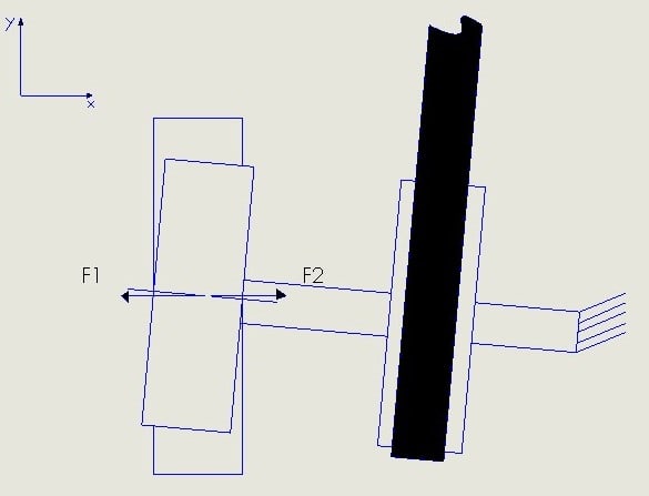
I have a question for you all about some (hopefully) basic theory about drives. The problem is visualized in the lower figure and will describe the circumstances. The round parts in the figure are wheels. One of them is made of steel and the other is made of rubber - both have roller bearings around the middle axis for spinning. It is intended that friction coefficient is high between these two materials because the rotation is translated with friction. The problem appears (as I see it) when the upper wheel axis bend a little bit out of centerline of rotation compared with the lower wheels (see the figure - this is caused by the outer forces applied and conditions). This causes some reaction forces in the x direction between the wheels (F1 and F2 - depending on the direction of rotation). Meaning that in our case the steel wheel is being dragged in the x-direction, since its mounting is significantly weaker than the mounting of rubber wheel.
Podporno_kolo_boben_slika_prava_jr8ehv.jpg


Basically my question is how to describe or where can I find any theory or examples on this kind of behavior? I would really like to somehow calculate those exact forces. And anyway I am only interested in the forces behavior in the +-x direction, although it would not harm to get to know the whole background. And just for me being completely convinced please confirm my physical model (the behavior).

Thanks upfront for your answers and best regards.

TheGasperus
 
Replies continue below

Recommended for you

That looks rather similar to a tire steering on a steel drum, for which there is a wealth of literature, and even test results.

Cheers

Greg Locock


New here? Try reading these, they might help FAQ731-376
 
In our particular case these wheels are actually friction gears not intended for a specifically hard job. One of the wheels keep climbing forward (in x-direction) and hitting other components in assembly producing noise (fatique) Therefore I would like to calculate the produced force between them and later strengthen the mounting structure to prevent deformations. Because I already know that we cannot prevent upper wheel (axis) to stay straight parallel with bottom axis.

Thank you and best regards.

TheGasperus
 
The sideways force is basically the contact force between the two wheels times the coefficient of friction. Not so complex. However, depending on what is bending/flexing etc to create the misalignment, the contact force may be larger or smaller than you think or intend.

 
You may not be approaching your problem correctly. This is a simple steering issue. Support the wheel in a way that if it is slightly out of alignment it steers into alignment, rather than further out of alignment. It is as though you have caster wheels on a cart pointed backwards. The solution is not to calculate the forces required to keep them from swiveling so that you can design a clamp that is strong enough.

You need understand how wheels and rollers work. Any point on the surface of a roller moves in a direction that is 90 degrees to the axis of rotation. When a roller contacts another surface, those points in contact must move together while in contact. There can be slippage or deformation of rubber that occurs if the axes of rotation are not in alignment. Apply these principles to solving your problem.
 
Hello again!

I am fully aware that my understanding of this problem is not particularly good. But I will describe the problem a little more in details. On the lower figure there is the same composition of steel wheel (gear 1) and rubber wheel (gear 2) just as it is in the figure in the first post. This pair of friction gear is intended to take care for the operating of secondary function in our machine (cooling) and it is also intended as support for the upper axis to prevent it to bend in the z-direction. As mentioned there is another steel wheel (gear) on the upper axis that provides operation of primary function of the machine. The force that is provided by the belt is causing the upper axis on which there are two steel wheels (gears) to bend for a small angle in y-direction (it cannot bend in z-direction since the mounting of rubber gear is very solid). That causes uneven alignment of the lower and upper axis. Yet the machine works good, only there is in my opinion some forces (F1 and F2) that causes upper wheels to climb in the y-direction and these forces are the one that interests me since the best solution I think so far is to stiffen the mounting wall of upper axis.

Slika_podpornega_kolesa_z_jermenom_prava_jfvquv.jpg


Thank you again.

Best regards.

TheGasperus
 
Now you have added belt tension force to the problem.

Ted
 
Yes, belt tension force provides enough friction force between left pair of wheels, but it is not directly important to my described problem. Belt is however providing force in -z and +y direction - it is not visible from the last figure (assuming -z direction is pointing perpendicularly in the monitor). The component of belt force in -z direction provides friction force between left air of wheels, while the component of force in +y direction results in bending upper axis a little bit. Since I now have upper axis little bit out of even alignment with lower axis, there I can return to my firstly asked question about resultant forces F1 and F2 which occurs between steel and rubber wheel.

I do not know how to possibly calculate forces F1,F2 or even physically describe the problem correctly. They basically cause deformation of the mounting wall visible in the last figure. My job is not align upper axis correct, but to examine the resultant forces between left pair of wheels and later provide corrections in the mounting area,that would be sufficient enough to get rid of deformation - regardless the resultant forces. But for optimization I definitely need some kind of force calculated or at least assumed force.

Thank you again.

Best regards.

TheGasperus
 
Do you know the tension in each side of the belt? Do you know the stiffness of the bearing and the shaft?

Cheers

Greg Locock


New here? Try reading these, they might help FAQ731-376
 
Yes, I know the tension forces on each side of the belt - that is where I get static friction force between the left pair of wheels. I also know the stiffness of the bearing and the shaft (and also stiffness of the rear mounting wall) - and I have concluded that the deformation appears on the rear wall, from the force resulted on the left pair of wheels.
 
handleman had it right. Multiply the force between the two by the friction coefficient of rubber on steel.
 
Status
Not open for further replies.

Part and Inventory Search

Sponsor