Continue to Site

Eng-Tips is the largest engineering community on the Internet

Intelligent Work Forums for Engineering Professionals

  • Congratulations SDETERS on being selected by the Eng-Tips community for having the most helpful posts in the forums last week. Way to Go!

Fuel Rail Supporting Mounts

JRCP

Automotive
Sep 21, 2022
1
Hi Everyone,


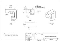
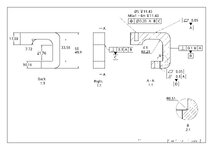
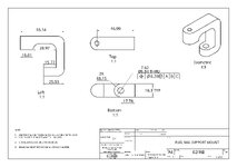
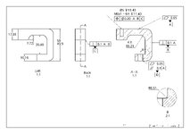
I’m still learning GD&T and could use your expertise. While I can design various simple parts in CAD, applying GD&T is where I struggle the most.


Could you take a look and let me know if this design is suitable for machining? What modifications or additions are needed to ensure accurate fitment? I’ve used millimeters, but I can provide the dimensions in inches if needed.


Thanks in advance for your help!

JRCP
 

Attachments

  • Part 1 Drawing 1 (Eng).pdf
    212.4 KB · Views: 22
Replies continue below

Recommended for you

Hi -- it looks like you might be using ISO-style of dimensioning. I say that because of the first-angle projection symbol in the title block, and the fact the you have commas instead of decimal points (although neither of those are necessarily ISO things). So the first suggestion would be to have a note that calls out a dim/tol standard (either ISO or ASME).

As far as the GD&T goes, most of the rules seem to be followed here. The circled "S" symbol is not used in either standard (it was in older versions of ASME, but I'd be surprised if that's the standard you'd be using). The dimensions linking the holes back to A, B, C should be basic dims, however.

Another suggestion: It's often best to have GD&T that relates A, B, and C to each other. So I might suggest a perpendicularity callout on B that ties it back to A. And then a perpendicularity callout on C that ties it back to A and B.
 
JRCP,

It looks like you are learning ISO GPS; there is no "GD&T" standard. See ISO 14638:2015 for the most recent description of the family of standards that make up that system. It falls under the ISO/TC 213, Dimensional and geometrical product specifications and verification. (Also, no "GD")

The other major standard series is "Dimensioning and Tolerancing", no "G", that is ASME Y14.5-(various years.)

The British have their own that is mainly a clone/duplicate of the ISO system.

In addition to what Garland23 mentioned, it's not great to dimension between tangencies. You've also double dimensioned the holes - each has a dimension from the flat on the right side, but then there is also another dimension between them.
 
Lots of dimensions and a lot of them can't be evaluated reliably if the general +/-0.1 from the note applies to them.
Now you have no choice but delete the +/-0.1, write UNTOLERANCED DIMENSIONS ARE TED, and specify a general surface profile relative to the main datum system (A,B,C ?).
 
Datum feature "A" is a primary one according to the feature control frame on your prints. You don't want to make it parallel to datum feature "D". It should be the other way around.
 
[A] doesn't have to be the base reference for all other features - it is primary only in the reference frame that matters. In the parallelism frame that controls [A], [D] is the primary datum feature. "Primary" is not universal for the part.
 
Feature "D" is too small to qualify for a primary datum. "A" is a primary datum feature not because of character "A" but rather the precedence of A/B/C in the feature control frames.
 
There is no rule concerning the size/extent of features to qualify for being a primary feature. If that is the surface that will orient the part in the installation, then it is what will also orient all other surfaces in the installation.

CMM operators love larger surfaces because it make their job easier, but that is without regard to the actual part function and can be damaging to the need.

"A" is a primary datum feature not because of character "A" but rather the precedence of A/B/C in the feature control frames.

No one said/wrote any different.
 
JRCP,

It looks like you are learning ISO GPS; there is no "GD&T" standard. See ISO 14638:2015 for the most recent description of the family of standards that make up that system. It falls under the ISO/TC 213, Dimensional and geometrical product specifications and verification. (Also, no "GD")

The other major standard series is "Dimensioning and Tolerancing", no "G", that is ASME Y14.5-(various years.)

The British have their own that is mainly a clone/duplicate of the ISO system.

In addition to what Garland23 mentioned, it's not great to dimension between tangencies. You've also double dimensioned the holes - each has a dimension from the flat on the right side, but then there is also another dimension between them.
What's the problem with the term GD&T?
It has been standardized for many years now to mean General Dimensioning and Tolerancing. Thinking that "G" stands for Geometric is as outdated as referring to a Position Tolerance as True Position.
 
What's the problem with the term GD&T?
It has been standardized for many years now to mean General Dimensioning and Tolerancing. Thinking that "G" stands for Geometric is as outdated as referring to a Position Tolerance as True Position.
It has not been standardized to mean that. Look at the ASME Y14.41 draft for an example.

gdt_y14.41.PNG

Note there is no matching definition for what constitutes "geometric dimensioning"

It a holdover from the original marketing materials from Lowell Foster and his "Geometrics" series of books and is used for marketing. It has no relevance to Dimensioning and Tolerancing per ASME Y14.5-2xxx and remains a distraction.

The only value is that those who use the term are identifying themselves as either producers of training material or those who operate without a copy of the relevant standards. Ignorance is bliss.
 
Last edited:
OP chose feature "A" as a primary. A primary datum feature can't be related to any other features. That is why it is called "Primary".
 
April fools jokes aside,
It seems to be common to refer to the use of geometric characteristic symbols placed in feature control frames as GD&T (yes, "Geometric" Dimensioning and Tolerancing).
Training materials seem to suggest that there is either a "traditional" method in which all tolerances are given as plus and minus or limits, and in contrast, there is the advanced and smart method called "GD&T". And the way that "better" way explained, usually, from some reason, results in people getting the impression that it's all about geometric characteristic symbols and feature control frames.

My personal opinion is that the bad and way too common tolerancing that should be put in contrast to what is being taught is not necessarily all plus and minus or as they commonly refer to it "coordinate tolerancing", but rather a poorly done mix of directly toleranced dimensions and feature control frames, while the feature control frames and datum feature identifications are the worse part of it - to the point that makes me sure that it would be much better if the drawing originator just stuck with the "old" "coordinate tolerancing" for everything.
 
A primary datum feature can't be related to any other features. That is why it is called "Primary".
Check out Fig. 6-30 of the standard (I can post pic here, if you don't have access). There's a position tolerance on the threaded feature that relates back to datum C as its primary datum. Yet datum feature C is itself tied back to A and B via a runout tolerance. Fig. 7-22 (a) is another example.
So it is possible for a primary datum feature to be related back to other features.
 

Part and Inventory Search

Sponsor