Eng-Tips is the largest engineering community on the Internet

Intelligent Work Forums for Engineering Professionals

  • Congratulations waross on being selected by the Tek-Tips community for having the most helpful posts in the forums last week. Way to Go!

Funtion of outlet Temperature Transmiter on AHU in Clean Room system? 1

Status
Not open for further replies.

SF6-146

Chemical
Sep 14, 2021
16
0
0
ES
Hi all,

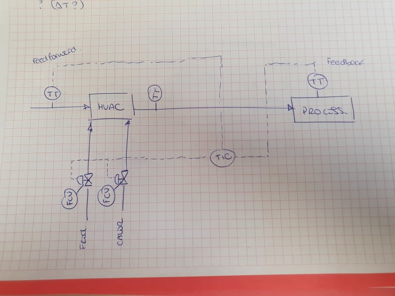
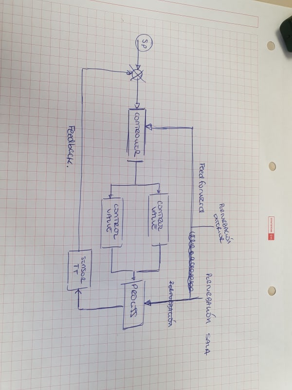
I have the following AHU system. I undestand that I have a Feedback control to control the Clean Room and a Feedforward control to control any exterior disturbance.

But there is a third TT at the outlet of AHU that I dont know what it used for... Any help / idea?

20220816_130703_bf5ltb.jpg


20220816_130655_rppcra.jpg
 
Replies continue below

Recommended for you

You mean the one in the middle? That is a discharge air sensor and controls the coils to meet a discharge air temperature. Maybe in your case it only monitors. but if you want to dehumidify, you need meet a specific DAT.
 
yes, but this TT is at the outlet, when all the process is end.

The main reson is not for controll outlet temperature in the deshumidification process.
 
Trying to understand your diagram and the control logic behind it, please correct me if I'm wrong:

1-You have setpoint on the return temperature that is user defined, for example between 19-25C
2-This will then feed into a supply air setpoint that is set not by the user, but by following a formula of a straight line where the solution is the setpoint supply air (say 12-18C)
3-Your third sensor is just to confirm that your supply air setpoint is able to be achieved and kept under control by opening/closing valves.

I'm not sure if my attempt to explain is clear to you, but I hope it helps.

 
I usually create a sketch that shows the system, the sensors (and what they read) and have written control sequences. All in the same view. This helps the controls contractor to implement what is desired. And it would help us here to understand what it is you want to do, or what it currently is doing. in the old days I used MS Visio to do that (and that is what many controls contractor use). Nowadays I use Revit details for that.

I'm just saying if you put the 2 sketches into one and write out a control sequence it may make things easier.

Yes, a DAT sensor would be at the end of whatever an AHU is doing to the air. You want to control the outcome (a temperature, or dew point, add pink pixeldust, or whatever you want) and based on current condition the logic decides what needs to change. If DAT is above setpoint, it will open the cooling valve. If DAT is below setpoint, it will throttle the cooling valve, or open heating valve. That 's how a feedback loop works, you need the feedback (DAT sensor in your case).
 
Status
Not open for further replies.
Back
Top