Continue to Site

Eng-Tips is the largest engineering community on the Internet

Intelligent Work Forums for Engineering Professionals

  • Congratulations KootK on being selected by the Eng-Tips community for having the most helpful posts in the forums last week. Way to Go!

Fuselage Inserts

Green 123

Aerospace
Feb 19, 2024
32
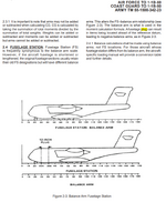
In weight &balance control and loading manual , Body Station (B.S.) is defined as a manufacturing location on the airplane. For first of an airplane model, B.S. are continuous from the front to the aft of the airplane. For later versions that are either stretched (i.e. fuselage inserts added) or shrunk (i.e. fuselage sections removed), B.S. becomes discontinuous, for manufacturing reasons.

what are fuselage inserts? and why is Body Station discontinuous when they are added to the fuselage?
 
Last edited:
Replies continue below

Recommended for you

when OEMs extend the fuselage they insert plugs (segments of the fuselage) rather than building an entire new fuselage ... cut the fuselage, spread apart, insert extra length, and rivet. Different OEMs treat the resulting fuselage differently. Most common is the leave the numbering (frame stations) as it was, so you start at FS0 run along until the first plug, then some different numbering till the end of the plug, now the fuselage stations continue as before (pre-plug). Some OEMs plan for these stretches, and have the nose of the plane as FS100, so they can plug and keep positive numbers. Makes sense to someone.

Yes, makes a PITA for the W&B. My suggestion is to replace true fuselage station with "X". Keep the middle of the plan the same, so that for the front spar frame (as an example) X is the same as fuselage station. Then let X map the fuselage fwd and aft. X will decrease towards the nose, initially matching the FS but then getting out of step in the plug and forward.

The other option, which I think is much more fiddly, to to replicate the build ... insert steps in the fuselage station so that the fuselage ahead of the plug has the old FS and the plug length is added by hand (and prone to error).
 
To expand a bit on the clear definition provided by rb1957, here is a bit of real world example. Boeing uses a special numbering system to identify the fuselage inserts. They do this (I guess, I am not Boeing) so that the major aircraft components such as landing gear, engines, wings, stabilizers, flight controls, etc., remain at the same station location and only the fuselage inserts have the special numbering scheme.

To the example for which I am quite familiar by experience:

For the Boeing NG (Next Generation series 737-600/700/800/900) the baseline aircraft with no fuselage inserts is the 737-600. To stretch to the 737-800 with which I am most familiar, Boeing installed a fuselage insert forward of the wings and another fuselage insert aft of the wings.

For the forward insert, they "sliced" the aircraft apart at frame station 500 (STA 500 in abbreviated parlance). From STA 130 (nose of the aircraft is 130" aft of the datum, thus there are no stations 1 thru 129 on the aircraft) thru STA 500, the station locations still match the actual inches from the datum. They install a 198" long fuselage insert consisting of nine 22" frame stations. The new frame stations are labeled STA 500A, STA 500B, STA 500C, STA 500D, STA 500E, STA 500F, STA 500G, STA 500H and STA 500I which then rejoins the aircraft. So for example the new location of STA 520 is actually 520" from the datum PLUS the new 198" fuselage insert. Therefore STA 520 is now 718" aft of the datum. STA 540 is 540" PLUS 198" or 738" aft of the datum, etc.

Something similar occurs with the aft fuselage insert where the aircraft is "sliced" at STA 727 but because of the forward fuselage insert STA 727 is actually 727" PLUS 198" from the datum, or 925" from the datum. Since the aft fuselage insert is 212" long, every station aft of the aft fuselage insert is 198" PLUS 212" added to the STA number to determine the location aft of the datum.

This is likely more detail than you wanted, but if you have to do any design work on Boeing aircraft with fuselage inserts, you will want to get familiar with this information. It usually can be found in the Boeing SRM Chapter 53, Boeing AMM Chapter 6 and Boeing centerline drawings, if you have access.
 
when OEMs extend the fuselage they insert plugs (segments of the fuselage) rather than building an entire new fuselage ... cut the fuselage, spread apart, insert extra length, and rivet. Different OEMs treat the resulting fuselage differently. Most common is the leave the numbering (frame stations) as it was, so you start at FS0 run along until the first plug, then some different numbering till the end of the plug, now the fuselage stations continue as before (pre-plug). Some OEMs plan for these stretches, and have the nose of the plane as FS100, so they can plug and keep positive numbers. Makes sense to someone.

Yes, makes a PITA for the W&B. My suggestion is to replace true fuselage station with "X". Keep the middle of the plan the same, so that for the front spar frame (as an example) X is the same as fuselage station. Then let X map the fuselage fwd and aft. X will decrease towards the nose, initially matching the FS but then getting out of step in the plug and forward.

The other option, which I think is much more fiddly, to to replicate the build ... insert steps in the fuselage station so that the fuselage ahead of the plug has the old FS and the plug length is added by hand (and prone to error)
Much obliged
 
To expand a bit on the clear definition provided by rb1957, here is a bit of real world example. Boeing uses a special numbering system to identify the fuselage inserts. They do this (I guess, I am not Boeing) so that the major aircraft components such as landing gear, engines, wings, stabilizers, flight controls, etc., remain at the same station location and only the fuselage inserts have the special numbering scheme.

To the example for which I am quite familiar by experience:

For the Boeing NG (Next Generation series 737-600/700/800/900) the baseline aircraft with no fuselage inserts is the 737-600. To stretch to the 737-800 with which I am most familiar, Boeing installed a fuselage insert forward of the wings and another fuselage insert aft of the wings.

For the forward insert, they "sliced" the aircraft apart at frame station 500 (STA 500 in abbreviated parlance). From STA 130 (nose of the aircraft is 130" aft of the datum, thus there are no stations 1 thru 129 on the aircraft) thru STA 500, the station locations still match the actual inches from the datum. They install a 198" long fuselage insert consisting of nine 22" frame stations. The new frame stations are labeled STA 500A, STA 500B, STA 500C, STA 500D, STA 500E, STA 500F, STA 500G, STA 500H and STA 500I which then rejoins the aircraft. So for example the new location of STA 520 is actually 520" from the datum PLUS the new 198" fuselage insert. Therefore STA 520 is now 718" aft of the datum. STA 540 is 540" PLUS 198" or 738" aft of the datum, etc.

Something similar occurs with the aft fuselage insert where the aircraft is "sliced" at STA 727 but because of the forward fuselage insert STA 727 is actually 727" PLUS 198" from the datum, or 925" from the datum. Since the aft fuselage insert is 212" long, every station aft of the aft fuselage insert is 198" PLUS 212" added to the STA number to determine the location aft of the datum.

This is likely more detail than you wanted, but if you have to do any design work on Boeing aircraft with fuselage inserts, you will want to get familiar with this information. It usually can be found in the Boeing SRM Chapter 53, Boeing AMM Chapter 6 and Boeing centerline drawings, if you have access.
Ta muchly
 
FYI ... appreciate the expressions of gratitude for our replies ... but we do have the LPS "Great Post!" as a way of showing that we helped ...
 

Part and Inventory Search

Sponsor