Eng-Tips is the largest engineering community on the Internet

Intelligent Work Forums for Engineering Professionals

G3 surface condition for a nose cone - help 2

Status
Not open for further replies.

78finn

Industrial
Jun 24, 2008
8
0
0
GB
Hi there,

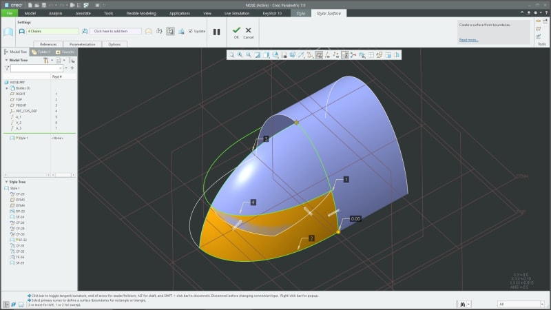
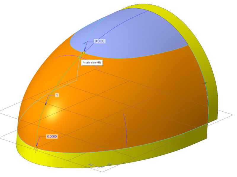
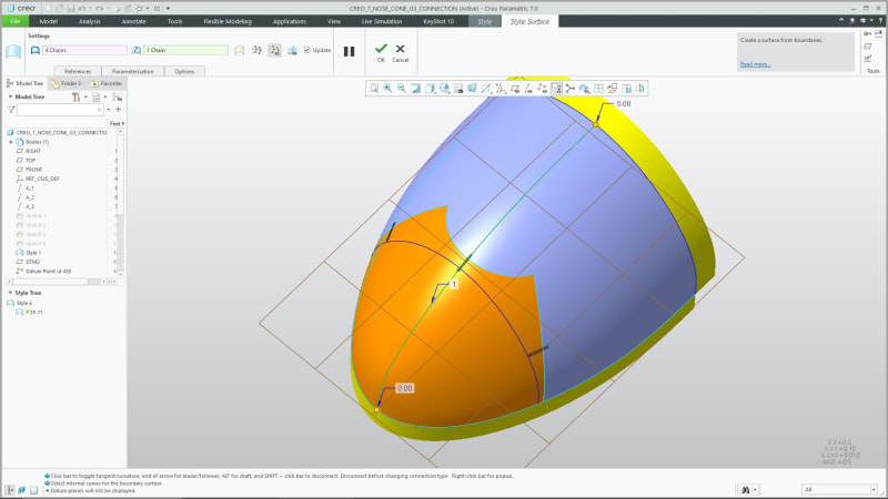
I am trying to model a nose cone/end surface with G3 surface conditions (as shown in the image below/ZIP file of model attached). I am using PTC Creo 7.0.

Nose_Cone_2_slxdyl.png


I have sketched a number of reference lines to control the length/width/depth of my surfaces, as well as adding ribbon surfaces. All of the spines in style have G3 end conditions (including the internal influencing spline). I am seeing the error reference a lot:

"The cross curves are not connected with the same continuity as the connection"

I am not sure what this error message is referring to or how I should be modelling this feature to achieve a G3 surface? If you can help me out, I would really appreciate it!
 
Replies continue below

Recommended for you

I would try contacting Bart Brejcha via Design Engine (company in Illinois) - this is a PTC Style module question and there are a lot fewer users for that. It used to be a ridiculously expensive license.
 
That message is about your top curve chain 2. If you notice the connection along that edge is only G2. The reason is that your internal cross curve IS NOT, in fact, connected with G3 continuity. You have no continuity connection defined on that curve where you are using it to construct the surface.

Redefine it so that it is G3, or create a different curve with G3, and then you will be able to achieve G3 along the top edge.
 
3DDave said:
I would try contacting Bart Brejcha via Design Engine (company in Illinois) - this is a PTC Style module question and there are a lot fewer users for that. It used to be a ridiculously expensive license.
Thanks, I will try that.

Greg McMurray said:
Redefine it so that it is G3, or create a different curve with G3, and then you will be able to achieve G3 along the top edge.
Yes, I have tried this. The chain 2 curve is G3, I have also tried creating a new G3 curve after the cut of the main surface, but this doesn't appear to work either unfortunately.
 
I see... it's likely because your primary chains 1 and 3 are not connected to the main surface with G3 continuity. You can perhaps visualize this better if you only build one half of the style surface. The curves must have G3 continuity defined at the top, and they clearly don't, having been defined by the trim.

This is a drawback of the trim strategy you employed. That was a good idea to get a 4 boundary surface, but not so much for surface continuity.
 
Image3_h2d8zj.jpg


On the other hand, perhaps you don't have to throw the baby out with the bathwater. Depending on your requirements you may want to experiment with trimming away different parts of the main surface.
 
Greg McMurray said:
On the other hand, perhaps you don't have to throw the baby out with the bathwater. Depending on your requirements you may want to experiment with trimming away different parts of the main surface

Are you able to achieve a G3 condition on all of those curves using the method above? Reason I ask is that I can achieve exactly what you have shown above with model I originally posted if I relax the other edge/surface conditions as you have. The thing i am struggling with is a G3 condition on the top, both sides, with a normal bottom condition.

Could you please share the model that you have created to this chat? I would find it useful, as I am sure many others would as well
 
I would also be interested to know how you achieved the driving blue surface in your model without a surface trim of some kind? Otherwise i assume a three sided surface perhaps?
 
Here is an example of of the trim surface with G3 connections on the side but not the top. I can also achieve a G3 connection on the top but not the sides. The technique I am using here is the same that I us in NX and it works well.

new_qugina.jpg
 
I would also be interested to know how you achieved the driving blue surface in your model without a surface trim of some kind? Otherwise i assume a three sided surface perhaps?]

No it was a trim. That's why I suggested you experiment with trimming different sections of the main surface.

As you mention, I don't see a way to get G3 on both the sides and the top. Again, this is the limitation of the trim method in Creo. The only other thing I can think of is model the nosecone first and build the other surfaces off of it. Then you can control the connectivity of all the subsequent curves.

Also, if this really does work in NX then file a bug report with PTC support. It shouldn't be that difficult for them to fix it if their competitors figured it out.
 
Greg McMurray said:
I don't see a way to get G3 on both the sides and the top. Again, this is the limitation of the trim method in Creo.

Yes, I think I agree with you here. I have been getting a bit closer of late (trying out a few things similar to your suggestion above), but still not quite there ‌‌...

Now trying to build the whole thing in ISDX (style), which really seems like the only way to go about it because trying to manage either a G2 or G3 curve as a conventional sketch in Creo is made incredibly difficult. ‌‌‌‌

All splines 7 degree. The trim doesn't actually appear to be the issue...which I think we both agree on.

As you can see, all surface conditions now G3, accept the final surface condition which is G2. Doesn't seem to matter which order I attempt (using this method - trim/top hat) the final surface condition maxes out at G2. This is probably absolutely fine for 95% of what I do, but would still nice to achieve a perfect G3...if that is even possible :)

1_xxcweq.jpg

2_jbii8s.jpg
 
Status
Not open for further replies.
Back
Top