Eng-Tips is the largest engineering community on the Internet

Intelligent Work Forums for Engineering Professionals

Gasket dimensions for Wafer type check valve and butterfly valve

Status
Not open for further replies.

coolniks37

Mechanical
Feb 7, 2013
85
0
0
CA
Hey everyone,

Need some advice on gasket dimensions for a 12" wafer-style butterfly valve connecting to a 12" B16.5 flat face flange. It's for an air line from a 10psi blower. Any insights on the ideal dimensions? Also, what adjustments are needed if I switch to an RF flange?

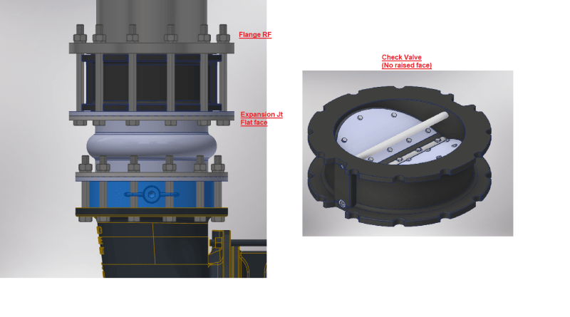
Similarly, facing a puzzle with a 12" wafer-style FF check valve. It's got a flat face flange on one end and a raised face flange on the other. Any suggestions for gasket dimensions? And how would those change if I opt for an RF valve?

Lastly, clueless about gasket thickness. Are there any guidelines or standards to follow? Any advice on determining the right thickness would be highly appreciated.


Thanks in advance!
 
Replies continue below

Recommended for you

Is it a wafer-style valve that clamps between two flanges? Or is it a flanged or lug-style valve?

"Wafer-style" and "flat face flange" are typically mutually exclusive, as a wafer-style valves typically sit inside the bolt circle of a set of raised face flanges.

Assuming the flange facings meet B16.5, just use standard gaskets for the two flange sets (full face gaskets for flat face flanges, typical spiral wound or similar for the raised face). Refer to ASME B16.20 and B16.21.
 
Thanks @akpipelineengr. The valve sits inside the bolt circle of the flange. The only issue here is that, the valve is flat face & has a raised face flange connection on one end & flat face expansion jt on the other end.
 
For the wafer type of butterfly or check valves, one should ensure there is no interference of the valve discs movement by the connecting gaskets and flange joints.
For connecting to a wafer type component or flange joint, be aware that a full faced joint should be used to ensure there is no stress concentration issue of the cast iron material between the mating surface.
 
Thanks mk3223 & akpipelineengr.
Pls find attached a snip of the arrangement. I am trying to finalize the gasket dimensions at both end of the valve.
Wafer_Check_valve_uvo2gs.png
 
Oh, I got it. That's a mess.

It's hard to tell exactly what is going on with that expansion joint, but those look like lap joint flanges with the expansion joint material at the face and a steel backer ring? If so, you can contact the manufacturer, but that expansion joint is really not meant to mate to anything except a flat face flange. 10 psi air service is pretty forgiving, but any bolt torque is likely to cause the backer ring to rotate and deform, and not seal properly.
 
IMO, the Air Blower is typically a cast iron (CI) equipment. It seems that the connection of the wafer butterfly valve on the Air Blow discharge could be a stress concentration issue to the CI material.
 
Thanks again mk3223 & akpipelineengr for your comments.

Considering the recommendation for a gasket by the valve supplier, I'm leaning towards a full face gasket on expansion joint end and a ring gasket on the other. Any concerns or alternative suggestions on this approach?

 
I would expect that in our work (municipal water works stuff), that a wafer-type check valve would be on a site with a whole bunch of other flat-face flanges and that whoever assembled it would just stick another full-face gasket in like all the other gasketed joints. Yeah, 90% of that gasket is then wasted, but doesn't really hurt anything, either.
 
Status
Not open for further replies.
Back
Top