New to this
Automotive
- Mar 7, 2023
- 3
Hi all,
I'm designing a shaft that has two halves that connect via bolted flange. I want to ensure that they're concentric, so I added a centering lip on one half to locate via LT1 fit in the other half. I'm concerned about the alignment of these two parts, so I started to look to GD&T to achieve some of my objectives. For example, I don't want the centering lip to cause the bolt patterns to be misaligned. However, I've never used GD&T, only basic dimensioning, or even taken a class... so I'm pretty lost.
Objectives:
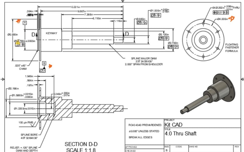
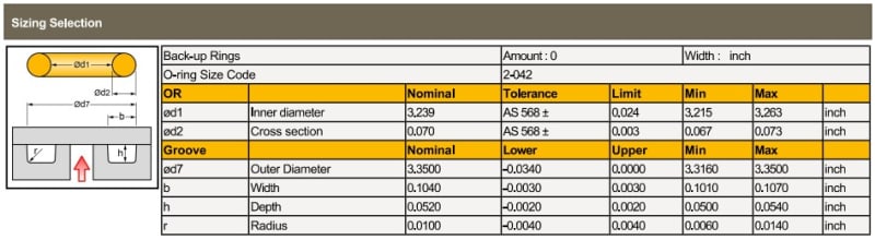
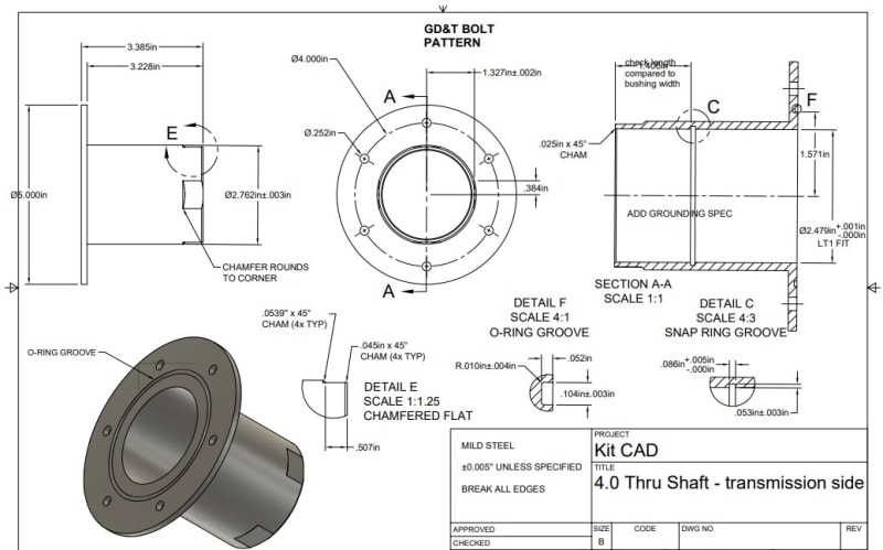
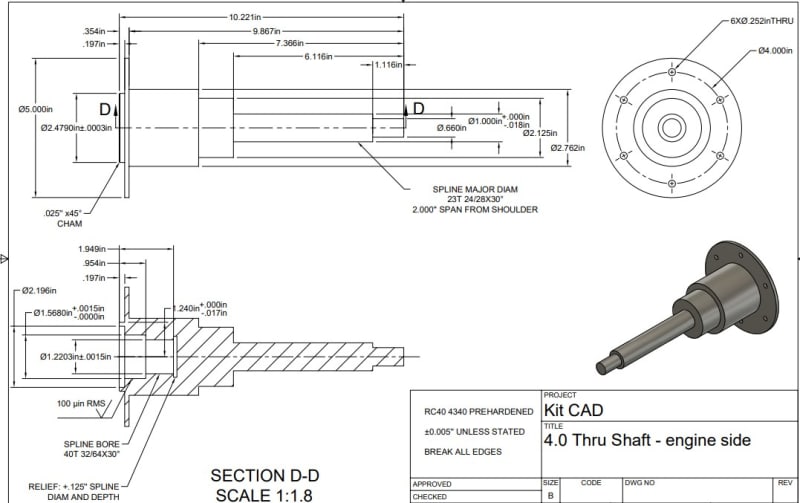
1. The mating faces of the flanges should be flat/parallel enough to each other so that the o-ring between them is compressed and seals properly. The groove for this o-ring has a height tolerance of ±.002'' (pic attached). So I think the control I add to achieve this needs to fall within that spec. I understand flatness will not ensure the two faces mate properly, because there is no datum for that control.
2. Once the two pieces are partially assembled via a hand press fit on the centering lip, I would like for the 6XM6 clearance holes on each flange to line up so that the bolts slip through and a nut can go on the other side of the flanges. I figure the centerline of each bolt hole in the pattern needs to be parallel to the respective half's centerline. I'm not sure this is the right way to go.
3. The shaft is around 1' long. So when both halves are assembled and being installed, I need one end to insert in an automotive transmission and the other end into the engine's crankshaft. I'm concerned if I don't put position tolerances on the shaft centers as the diameter varies, we may have trouble mating the engine to the transmission if the shaft centers are misaligned enough.
I can update my drawings to have GD&T but before I learn it, I want to confirm that it's the right tool for the job and that I'm thinking about it correctly first. So drawings without GD&T and just basic dimensioning are attached. Please excuse my notes, this is a draft. This part is a one-off part. Potentially to be produced in higher volumes later. If I'm over engineering by using GD&T at this phase, there's a subset of what I've said here that's useful or there's something I'm not considering let me know! Thanks.
I'm designing a shaft that has two halves that connect via bolted flange. I want to ensure that they're concentric, so I added a centering lip on one half to locate via LT1 fit in the other half. I'm concerned about the alignment of these two parts, so I started to look to GD&T to achieve some of my objectives. For example, I don't want the centering lip to cause the bolt patterns to be misaligned. However, I've never used GD&T, only basic dimensioning, or even taken a class... so I'm pretty lost.
Objectives:
1. The mating faces of the flanges should be flat/parallel enough to each other so that the o-ring between them is compressed and seals properly. The groove for this o-ring has a height tolerance of ±.002'' (pic attached). So I think the control I add to achieve this needs to fall within that spec. I understand flatness will not ensure the two faces mate properly, because there is no datum for that control.
2. Once the two pieces are partially assembled via a hand press fit on the centering lip, I would like for the 6XM6 clearance holes on each flange to line up so that the bolts slip through and a nut can go on the other side of the flanges. I figure the centerline of each bolt hole in the pattern needs to be parallel to the respective half's centerline. I'm not sure this is the right way to go.
3. The shaft is around 1' long. So when both halves are assembled and being installed, I need one end to insert in an automotive transmission and the other end into the engine's crankshaft. I'm concerned if I don't put position tolerances on the shaft centers as the diameter varies, we may have trouble mating the engine to the transmission if the shaft centers are misaligned enough.
I can update my drawings to have GD&T but before I learn it, I want to confirm that it's the right tool for the job and that I'm thinking about it correctly first. So drawings without GD&T and just basic dimensioning are attached. Please excuse my notes, this is a draft. This part is a one-off part. Potentially to be produced in higher volumes later. If I'm over engineering by using GD&T at this phase, there's a subset of what I've said here that's useful or there's something I'm not considering let me know! Thanks.