Eng-Tips is the largest engineering community on the Internet

Intelligent Work Forums for Engineering Professionals

GD&T for hinge holes

Status
Not open for further replies.

MattEdwards

Mechanical
Mar 19, 2024
12
0
0
GB
I have a grey part (A) with two concentric holes, that form a hinge along with a blue mating part (B) and two pins:
simplified_ovhjnx.png

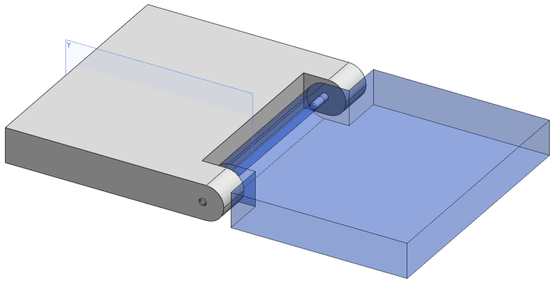
I want to ensure that part B will be aligned with datum Y on part A once assembled, so need an axis between the two holes in A to be perpendicular to datum Y. I can think of two ways to do this:
- Make one of the holes a datum, and align the other two it using true position
TP_rbsiqg.png

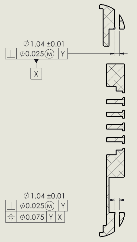
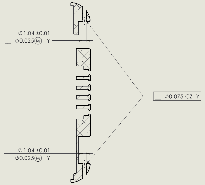
- Use a single perpendicularity tolerance attached to both holes with common zone (CZ)
CZ_pucs68.png


Are there any other ways? Which way is best?

I'm in the UK working to ISO standards, but interested to hear standard practise for ASME too.

Cheers,
Matt
 
Replies continue below

Recommended for you

You could use the bottom large flat surface of Part A as Datum A, the left edge as Datum B, the us a positional tolerance to locate the pin holes on Part A. You'd have to do an MMC tolerance stackup of the assembly to figure out what kind of positional tolerance you can get away with. If necessary, you could also add a projected tolerance zone for the pin holes.
 
Since the two coaxial holes have the same functional role and one does not "lead" the other in any way, I wouldn't use one of them as a datum reference for the other.

Under ISO GPS, I guess you can control their alignment by using the CZ modifier with the perpendicularity specification, as you did.

Under ASME Y14.5, you could do the same by using the CF (Continuous Feature) modifier, but a more typical approach to this would be using a tolerance of position with reference to Y and "2X" preceding the diameter dimension. Positional tolerance in ASME Y14.5 is the agreed-upon tool for alignment or grouping of features of size. In such cases, it's OK if the holes are only oriented relative to the datum (Y in your case), and not necessarily located relative to it. You could even specify the positional tolerance without any datums, and then designate the group of aligned holes as datum feature A, and use it as a primary datum reference elswehere, if appropriate.
 
Thanks Burunduk, very useful.

So using positional tolerance in ASME, would that be a composite frame, with the upper frame locating the pattern with |⌖|⌀0.025|Y|, and the lower frame relating the holes to each other with |⌖|⌀0.075|Y|?

Do you think this would be preferred to using perpendicularity with CZ under ISO GPS?
 
If you would want to use a composite position frame under ASME you would need a two-rows frame with a single "⌖" symbol. The looser value would be on top and in your specific case it would only be defining the (coaxial) zones limiting the orientation devition. The bottom row would be with a tighter tolerance aligning the two hole axes together, and not referencing any datum. You can't make the tolerance relating the holes to each other looser than the one relating them both to the datum, that would be redundant because the tighter control will effectively align them up to the tighter tolerance value. I'm not sure whether it is better or worse than the ISO scheme with the CZ modifier you showed in your second drawing. It depends on what exactly your functional requirements are and why you chose the tolerance valeus that you did. 
 
Status
Not open for further replies.
Back
Top