Continue to Site

Eng-Tips is the largest engineering community on the Internet

Intelligent Work Forums for Engineering Professionals

  • Congratulations IDS on being selected by the Eng-Tips community for having the most helpful posts in the forums last week. Way to Go!

GD&T: Part w/o locking datum feature. How to inspect? 2

Status
Not open for further replies.

cmmguy75

Mechanical
Jan 25, 2014
22
Hi All,
I guess this is an old question but I still see drawings here and there showed NO LOCKING DATUM FEATURE.
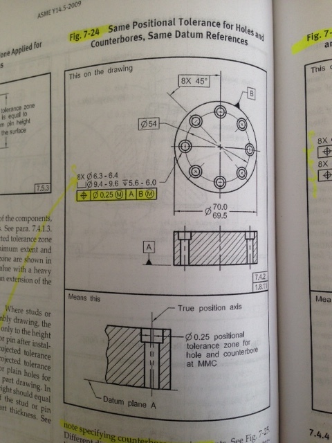
Please see attached picture which is from ASME Y14.5-2009, page 121. The basic 8x 45deg is from vertical line to center of |B| and center of a hole.
For calculating the TP, we need to get actual angle (nominal=45deg) and radius (nominal=27).
The angle here is from hole to hole. So it means I can use any of these holes to lock the part, here the one@12:00?
Is that the way?
Thanks!
GD_T_7-24_wjxeuk.jpg
 
Replies continue below

Recommended for you

Yep. You can lock onto any of the holes as the first one to measure. There is no clocking datum of the pattern, but within the pattern the angular spacing must be maintained (within the given position tolerance). Also note the "M" modifiers, which I could factor into a more detailed answer, but I hope you get the main idea for what you were asking.


John-Paul Belanger
Certified Sr. GD&T Professional
Geometric Learning Systems
 
I would say this is very common dillemma amongst CMM guys, because from CMM inspection perspective the easiest situation is when the coordinate system (datum reference frame) is fully constrained in terms of rotation and translation.

The thing is this drawing does not say in any way that the last rotation about datum axis B shall be constrained during inspection of the positional requirement for the pattern. In consequence, it does not say anything that any of the holes shall be used to constrain that remaining rotational degree of freedom. The drawing requirement is to check if axes of all 16 features (8 thru holes and 8 counterbores) simultaneously lie inside a pattern of 16 cylindrical tolerance zones that are perfectly perpendicular to datum plane A, located at basic diameter 54 about datum axis B, and circumferentially spaced basic 45 degrees apart. The tolerance zones are free to rotate about datum axis B. On CMM level this basically means that once CMM finds actual axes of those 16 features, it should use a best-fit routine to check if it is possible to virtually rotate the pattern of the tolerance zones as described above and fit it over those actual axes, so that the axes fully lie inside the tolerance zones. If that is possible, position of the features is good.

That being said, if you use one of the holes as a quasi-tertiary datum feature, you will be checking position of the pattern against slightly different, and unfortunately tighter, requirement than the one defined on the drawing. This in turn means that if your inspection results show the pattern is good, it will also have to be good if checked according to what print really requires. But if you results indicate the pattern is not good, it will not necessarily mean the pattern does not meet drawing requirement.
 
Pmarc,
Why is tighter? I am not saying is not, I am asking why?
Thank you very much for your activity here on eng tips. I have learned alot from you.
 
Thanks guys.
Paul, so you means it should be use BEST FIT technique to check these holes? I've not tried to use best fit on my cmm running with Mitutoyo Mcosmos.
How about another drawing attached here? The whole is not line up with any axis. Can I use one in 1st quadrant to lock then rotate -45deg?

 
 http://files.engineering.com/getfile.aspx?folder=e18de224-b8cf-42de-b012-d0429bb79966&file=TruePostion_of_a_BC.jpg
That's the same case, you have the ID as datum axis D.

----------------------------------------

The Help for this program was created in Windows Help format, which depends on a feature that isn't included in this version of Windows.
 
greenimi,

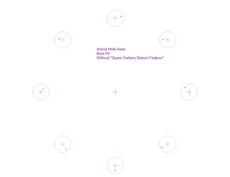
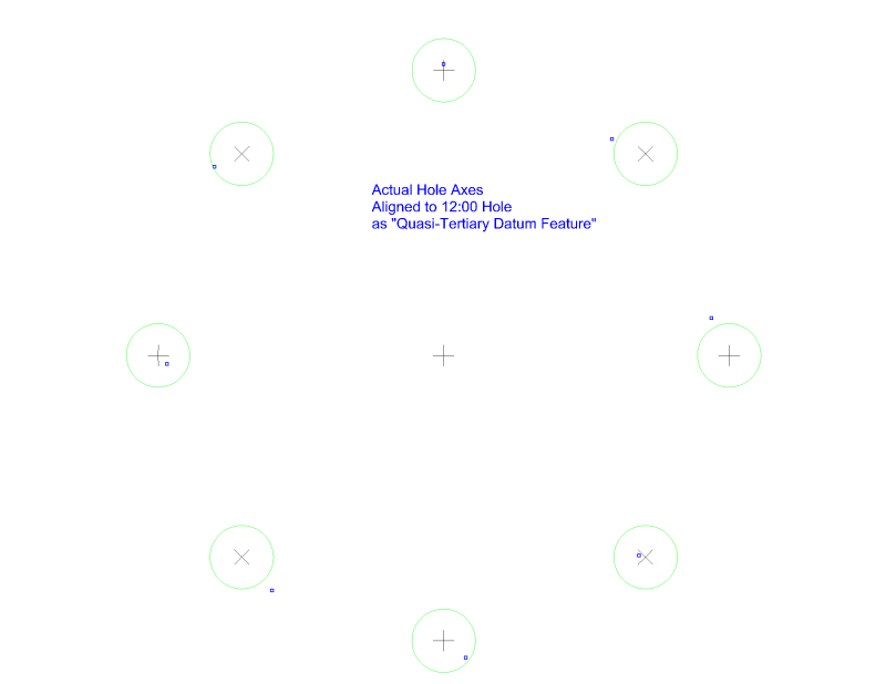
Pmarc is completely correct. But I was thinking about why the requirement is tighter, and it's kind of hard to explain in words. Pictures are so much easier. So here are a couple of figures that show why adding a "quasi-tertiary datum feature" becomes a tighter requirement. The crosshairs are the true positions, the green circles are the tolerance zones, and the points are actual hole axes:

Pattern_Best_Fit_ccennc.png


Pattern_Aligned_to_1200_Hole_bxqc5i.png


In the best fit scenario, the 12:00 hole deviates mainly in the clockwise direction and some other holes deviate counterclockwise. But all of the holes are inside their zones.

If the 12:00 hole is added as a tertiary datum feature, we can't "balance" the extreme clockwise and counterclockwise deviations anymore. We must align the pattern to the 12:00 hole, to give it zero deviation in the clocking direction. Then some of the other holes are too far counterclockwise and fall outside their zones. This is an example of what pmarc described.

Evan Janeshewski

Axymetrix Quality Engineering Inc.
 
Thank you, Evan. This is exactly what I meant.
 
Yes, thanks Evan! That's exactly what I was referring to (about the "M" modifier) in my brief first answer.

John-Paul Belanger
Certified Sr. GD&T Professional
Geometric Learning Systems
 
J-P,
I have to ask. What does the "M" modifier have to do with Evan's reply?
 
If there were no MMB, then while you'd have the ability to rotate the 8 axes freely, you would lose the ability to shift them around datum axis B. This datum shift is another aspect of the "best-fit" routine mentioned in your first reply that factors into the inspection.
So in my quickie answer, it is still true that he can pick any one of the holes if he really needs a clocking feature. But you and Evan clarified that while this may be OK if the part then meets the position tolerance, if it seems to be out of tolerance then we can't reject it -- he'd have to pick another hole or ideally the best-fit approach.

John-Paul Belanger
Certified Sr. GD&T Professional
Geometric Learning Systems
 
Speaking about datum shift at CCM (B at MMC here) my dilemma is how the CMM is talking care of this shift?

We know from the theory point of view that:
"The maximum amount of datum feature B shift that you are allowed to use is a half of difference between size of actual related mating envelope (RAME) of datum feature B (this envelope is perfectly oriented and located, if applicable, relative to primary datum A) and the size of virtual condition (also called maximum material boundary, MMB) of datum feature B."

So, how you measure this part? First measure datum feature A and create datum plane A. Then measure the cylinder –OD- to get its axis in order to create the coordinate system.

Now, if the axis is not perfectly perpendicular to datum A (and will never be, --probably) THEN to get datum shift B, are you “re-measuring” datum feature B (again) to obtain the size of RAME? Or the CMM can get that “adjustment” automatically?

Since Evan, pmarc and J-P B are on this thread I expect to get some traction on this “new problem”.
 
greenimi,

Short answer for now.

It is likely that the CMM is not accounting for the shift, and it depends on the capabilities of the CMM software and the programmer using it. In many (possibly most) cases, datum features referenced MMB are treated in CMM inspection as though they were referenced RMB.

To account for the shift properly, the CMM software must somehow approximate the shifting that would occur on a physical gage with fixed-size datum feature simulators. This is not straightforward, and CMM softwares vary widely in their ability to perform these "soft gaging" calculations.

Evan Janeshewski

Axymetrix Quality Engineering Inc.
 
For A: no
For B: Yeah, they probably should have. This is because B is to be simulated at MMB, which is different than MMC. (For completeness, a secondary datum feature should be tied back to the primary datum feature.)

John-Paul Belanger
Certified Sr. GD&T Professional
Geometric Learning Systems
 
Status
Not open for further replies.

Part and Inventory Search

Sponsor