Continue to Site

Eng-Tips is the largest engineering community on the Internet

Intelligent Work Forums for Engineering Professionals

  • Congratulations waross on being selected by the Eng-Tips community for having the most helpful posts in the forums last week. Way to Go!

GD&T How to control a hole on a moving assembly?

Frokilin

Mechanical
Feb 6, 2025
5
Hi,

I have this assembly where the green part is attached to the blue one, but green part can rotate around the attachment axis to the blue part. The distance from the holes on the blue part to the hole on the green is critical. Being B and C the holes on the blue part, I am wondering how I could callout the Hole on the Green part.
My concern is that if a CMM is used and they don't set the green part nominally with respect to CAD, it will show Out of Spec when in reality it could function as desired.
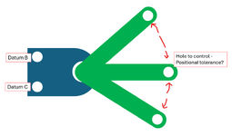
1738876795709.png
 
Replies continue below

Recommended for you

The way I would recommend specifying this is to start by specifying how the part is to be fixtured for measurement, with the green arm in a certain position relative to A-B-C, probably in the 3 o'clock position. You can specify the required fixture tolerance, too, as it will subtract from what you have available for part tolerance. Then specify the hole position to A-B-C. You may also need to consider the clearance in the pivot joint, and specify that the green part is pushed all the way left or all the way right.
 
OP
you don't, it's dimensioned at the detail level.
before assembly. and it had to be tolerance
to meet or exceed dimensioning after assembly
 
Is that a part with 3 arms and 3 holes or a single arm with a single hole in 3 positions?

Why is it important to make this specification at the assembly level? Are the hole(s) drilled at the assembly?

Can the requirement be specified at the individual part level?
 
Part is a single arm that can rotate around the hole.

There are drawings at part level and stack up has properly been done, but I need the assembly level drawing as well with that hole called out.

I tought about a fixture like has been metioned avobe, with the proper GR&R to make sure it's good, but I wanted to avoid it if possible, and just have a callout where the green part can rotate and not needed to be fixed to a position. I was thinking about using customized DRF but wanted to see if there is other potential solution.
 
My suggestion is to hold dimensions at the detail level, use a go no go inspection fixture after assembly. If it's a high volume part.
 
With a CMM one could lock the arm in 3 different widely spaced locations, find the center point of the hole; from that construct a circle and find the center of the constructed circle. This gives the radius to the hole and the pivot location. Then check the center location relative to the datum holes.

I think you will have to add this as a note.

If the individual parts are acceptable, is the idea to reject them at the assembly level?

That seems very expensive as all the components in the stack are going back to inspection. It also means that if any of the parts ships as spares there is a chance a customer will be screwed by using in-tolerance parts and ending up with an unusable assembly.
This is a good idea, but I kind of wanted to have it as simple and faster as possible. That's why I was thinking on the customized DRF.

If parts are in spec at part level they won't be rejected at the assembly level.
Assembly level drawing will come from the stack up, so spares part should work as well too, although customer of this assembly will be within the same company. Assembly is way more complicated that what shown in the picture, adding manufacturing fixtures and processes in the mix.
We want to have the assembly level drawing to do sampling inspection to kind of understand the process capability including manufacturing process and to have a target to achieve. Also it will help root causing issues if needed.
 
CMM is a very effective inspection method and works well. how ever a CMM has high work load and is normally very back up.
try to use simple tooling methods that is very fast and efficient. in accordance to APQP
efficiency is wording is not used any more.
but this OG does lol
 
CMM is a very effective inspection method and works well. how ever a CMM has high work load and is normally very back up.
try to use simple tooling methods that is very fast and efficient. in accordance to APQP
efficiency is wording is not used any more.
but this OG does lol
Thanks for your thoughts! Is not that we will measuring in the CMM every single of these assemblies, but we need the Assembly level drawing, that was why I wanted to know the best wat to call that hole out in the drawing. If later we measure a few times on the CMM and then use more often a gage to check it, still TBD. But we do need the drawing.
Agree with you that probably a checking gage would be a fast and accurate enough method overall, I also may be guilty of using the CMM too much :')
 
The customized DRF allows some vector components of the constraints applied by the referenced datum feature to be ignored. There isn't anything about puppeting an assembly into a particular configuration. For that you need a note.

Sampling and process capability are not an engineering requirement and should not be on an engineering drawing. The should be considered in making tolerance analysis decisions and , I suppose, one could spec tolerances on a statistical basis like normal distribution of 1 sigma deviation = 0.01 , 3 sigma = 0.04 allowed, and some limit on kurtosis, et al. I don't believe I have ever seen anyone do that, but with good feedback from production one certainly could.

I know it is popular for QA/QC to get engineering to do their job for them and to try to use the engineering drawing as the repository of manufacturing and quality assurance information. I also know that what I don't like may be a situation you are still stuck with. You have my sympathy.

Create a process for doing that inspection and specify how the parts are to be positioned, all the steps, and the data to be collected. The engineering work is to ensure that all the individual parts, assembled per the assembly drawing function as they should. There should be no engineering need to check engineering's own work which is what a tolerance requirement on the assembly will do.

If necessary, create a note on the engineering drawing referencing that process and everyone will be unhappy but they probably won't be able to turn it down.

Appreciate your answers, as you said, unfortunately I am kind of stuck with the creation of that drawing. I understand your reasoning but let me explain the "workflow" that I have in mind, it kind of makes sense in my head but I might be wrong:
  • Part level drawings are created, and parts will be inspected as per the drawing (for quality to determine frequency etc)
  • Through a tol stack-up, including all the parts and manufacturing fixtures affecting that green hole, we get the variation expected for that hole at the assembly level, back to the assembly level datums (in this case, also blue part level datums)
  • Then call out the green part hole with something like this (assuming A is the base of the blue part) --> POS | øX. X | A[z, u, v] | B -C[ x, y] |
    with this callout I think that green hole could rotate freely around w (Z axis) and then I would avoid having it in a set position, using a fixture to set that position etc
  • Drawing won't include any sampling frequency nor process capability needed. It would be more of a quality/manufacturing tool to help them understanding the process. That drawing purpose is for them to have something to check against, at the assembly level, if needed.
I have seen in a couple of different industries drawings at subassembly level, and those subassemblies being inspected periodically. And also just by having the subassembly level drawing, it could speed up some root causing.
Simplifying it a lot, If 2 subassemblies are to be attached together and they fail, I think is faster to check them at the subassembly level and see which one is failing, than going, for both subassemblies, part by part, including manufacturing tooling fixture, to check what is wrong. This is not even throwing in the equation, welding or paint processes that could deform parts. I agree that should be engineers work to short that out and have a good design, but unfortunately things in production don't always work as expected, specially in early phases and when production is ramping up, or there could be external factors that may affect as well.
 

Part and Inventory Search

Sponsor