Continue to Site

Eng-Tips is the largest engineering community on the Internet

Intelligent Work Forums for Engineering Professionals

  • Congratulations SDETERS on being selected by the Eng-Tips community for having the most helpful posts in the forums last week. Way to Go!

GDT Bent Sheet Metal Parts

nmine

Mechanical
Jul 7, 2023
12
Hi,

I have started to design a lot of bent sheet metal parts. I am comfortable using GDT on machined parts or flat sheet metal parts but applying it to bent sheet metal parts can be sometimes confusing. For parts like the one below, is it easier from an inspection position to use profile tolerances to control the outer edge/surfaces or just regular plus/minus linear and angular dimensions/tolerancing. With parts that have a lot of bends it seems if you use profile tolerance with respect to your datums, they need to be large to accommodate the position and angle deviations. In the part below if you want to control the angle tighter than the position of the surface, should you use a larger profile tolerance on the surface to control position and then an angularity tolerance to refine the angle or just remove basic dimensions and use regular linear and angular tolerances? When it comes to datums, it seems hard to have just one setup as the larger profile tolerances needed could allow some of the features to interfere. What is the best way then to dimension and tolerance parts like below? Thank you for the assistance.
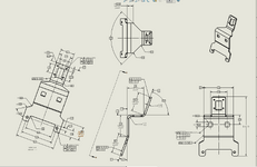
1743695941362.png
 
Last edited:
Replies continue below

Recommended for you

When designing sheet metal parts, holes should generally be placed at least 2.5 times the material thickness away from bends and edges to prevent deformation or tearing during fabrication.

Here's a more detailed breakdown:
  • Distance from Bends:
    • Holes should be located at least 2.5 times the material thickness plus the bend radius away from any bends.

    • Slots should be placed at least 4 times the material thickness plus the bend radius away from the bend.
  • Distance from Edges:
    • Holes should be placed at least 2 times the material thickness away from an edge to avoid a "bulging" effect.

    • For extruded holes, place them at least 3 times the thickness of the sheet from the edge to avoid deformation or tearing.
  • Hole Size:
    • Hole size should be at least 2.5 times the material thickness.

    • For thin parts (0.036 in. (0.914mm) or thinner), a hole size of 0.062 in. is recommended.
  • Hole Spacing:
    • Holes should be separated from each other by at least 6 times the material thickness.
  • Notches and Tabs:
    • Notches must be at least the material thickness or 0.04 in. (1.016mm), whichever is greater, and can be no longer than 5 times its width.

    • Tabs must be at least 2 times the material thickness or 0.126 in.
  • Countersinks:
    • Keep a minimum distance of 3 times the material thickness from a bend, 4 times from an edge, and 8 times from each other.

    • Countersinks shouldn't be deeper than 0.6 times the material thickness.
  • General Tolerances:
    • Forming and bending: ±0.010″ to ±0.030″ depending on complexity.

    • Hole locations: ±0.005″ to ±0.015″ typical.

    • Overall part dimensions: ±0.015″ to ±0.060″ based on size.

    • Feature-to-feature: ±0.010″ to ±0.030″ typical.
 
Hi,

I have started to design a lot of bent sheet metal parts. I am comfortable using GDT on machined parts or flat sheet metal parts but applying it to bent sheet metal parts can be sometimes confusing. For parts like the one below, is it easier from an inspection position to use profile tolerances to control the outer edge/surfaces or just regular plus/minus linear and angular dimensions/tolerancing. With parts that have a lot of bends it seems if you use profile tolerance with respect to your datums, they need to be large to accommodate the position and angle deviations. In the part below if you want to control the angle tighter than the position of the surface, should you use a larger profile tolerance on the surface to control position and then an angularity tolerance to refine the angle or just remove basic dimensions and use regular linear and angular tolerances? When it comes to datums, it seems hard to have just one setup as the larger profile tolerances needed could allow some of the features to interfere. What is the best way then to dimension and tolerance parts like below? Thank you for the assistance.

View attachment 7721
Other than the hole vs sheet metal thickness
Should be OK. Tolerances are liberal.
Parts are small so may require Punch and stamp.and will require developing for spring back.
 
As usual, it depends. if the function of the part requires it, this is generally how it would be done.

One thing that is interesting is the use of extra datum features beyond those identified as A, B, and C for some of the profile tolerances for features that are on surfaces surrounded by a profile that is defined from references to A, B, and C.

It is unfortunate that the ASME Y14.5 standard creators do not have angular variation geometric characteristic controls - angularity is often just a substitute for the profile of surface geometric characteristic and don't directly control angular variation.
 
Thanks for the feedback! @3DDave I find that when everything is referenced back to ABC, features can move too much and the fix is just make the profile tolerance large enough to accommodate which can introduce further issues. For example, the 2.8 mm holes, If I did not have a new D datum, I would need to apply a large position tolerance on the holes which is fine, but I also mainly care about their orientation to datum D and position to each other for assembly purposes (hence datum D). Then the cutout in the center of the holes is clearance for a connector. So what matters is the holes position to this cutout (or vice versa) firstly and then secondly to datum ABC. In instances like this when you have multiple components interacting with the bracket, does it make more sense to have more than 1 setup? Further, does it make sense to have a large profile tolerance around the edge with respect to ABC to control position/orientation and then a tighter one to control just form? Lastly what is your solution for the position/angle of a surface? Thanks.
 
Parts are so small I doubt angular error will have much effect. I also thought about the angles.

Bigger problem is the hole size it can't be punched
 
Hi @mfgenggear all of the parts I am designing will be laser cut/CNC press brake due to small qty. The design will change long before we get to stamping quantities if ever they do. I do have larger parts where I would like to leave more room for linear deviation where angular is more important though....
 
Hi @mfgenggear all of the parts I am designing will be laser cut due to small qty. The design will change long before we get to stamping quantities if ever they do. I do have larger parts where I would like to leave more room for linear deviation where angular is more important though....
If that is the case , if laser cut it will be repeatable well as stamped.
If a flat pattern cut it will be a PITA, because they are so small to handle but that's the manufactures task. It will require second handling or operations to leave excess and maybe with tooling holes. To locate during bending. I would stamp bend these.
And not brake form. Then the end would have to be trimed off.
Look at radius and the wall thickness.
 
Often with sheet metal and generally flexible parts a restrained condition is specified. It reduces the variation you have to limit and allows more functional controls that represent the assembled state. Then maybe smaller profile tolerances can be handled and less need for refinements. There are several examples throughout ASME Y14.5.
 
Often with sheet metal and generally flexible parts a restrained condition is specified. It reduces the variation you have to limit and allows more functional controls that represent the assembled state. Then maybe smaller profile tolerances can be handled and less need for refinements. There are several examples throughout ASME Y14.5.
That is a good point, however these parts are so small I don't believe it will be an issue.
But a functional gage to verify parts will assemble satisfactory. Spring back will require developed.
 
I had one part that was complex with non-parallel bends and no right angle bends; I ended up making the drawing of the flat part - all very simple profile and position geometric characteristic controls and specified bend lines and bend angles to form it. In your case, the holes relative to the openings won't change between the flat part and the formed part.

The problem likely for your part is that some very large variations in some aspects are allowable, but some details have to be well controlled; this ends up with layer on layer of things to check.

Maybe the best is to have larger profile of surface tolerance and use flatness to keep the part from getting out of hand.
Did this include the setbacks in the flat pattern
 
So then for FAI, would the supplier supply both a flat pattern and then a bent part to inspect?
 

Part and Inventory Search

Sponsor