Continue to Site

Eng-Tips is the largest engineering community on the Internet

Intelligent Work Forums for Engineering Professionals

  • Congratulations IFRs on being selected by the Eng-Tips community for having the most helpful posts in the forums last week. Way to Go!

GE D60 v5.7x ground distance setting

Status
Not open for further replies.

marks1080

Electrical
Oct 10, 2006
613
Hello All,

This question is specific to setting the GE D60 line protection relay. I'm working with firmware v5.71 if that makes a difference...

I'm using CAPE to get my fault and apparent impedance values.

I am defining ZL0/ZL1 in my settings file. Both values are obtained from CAPE. My understanding is that this is being used by the relay to calculate K0 based upon my Zapp max from CAPE.

When I set my zone 1 ground reach, which I have defined as 0.75 * ZL1 (positive seq. impedance), I take the primary ZL1 value from CAPE, multiply it by my CT/PT ratio to get my secondary value, then multiply by 0.75 and enter this value (mag and angle) into the setting file.

Now, to my actual question:
When I am setting the Z2 ground reach setting, I am using the definition 1.25 * (ZMA SLG), where ZMA SLG is the maximum apparent impedance from CAPE for a single-line to ground fault at the remote end. When I use my ZMA SLG value from CAPE I should also use the CT/PT ratio to find my secondary value. !BUT! do I apply zero-sequence compensation to this value prior to entering it into the settings file? I know I've already defined ZO/Z1 in the settings file, which is used for the relay to do zero-sequence compensation, specifically when it is doing its angle compare functions on measured vs. memorized values. I'm unsure if I should be using a (K0) compensated value of the Zapp max SLG value, which CAPE can give me quite easily, or do I simply enter the Zapp max SLG (secondary) value and let the relay do the compensation on the reach value on its own.


In summary,

When setting Z2 ground reach setting for the D60 should I apply zero-sequence (K0) compensation to my reach values prior to entering into the settings file.

Thanks in advance!
marks1080
 
Replies continue below

Recommended for you

Bump.

Interested if anyone has dealt with this before. I had expected to get more replys.

Thanks!
Mark
 
If I understand you correctly,

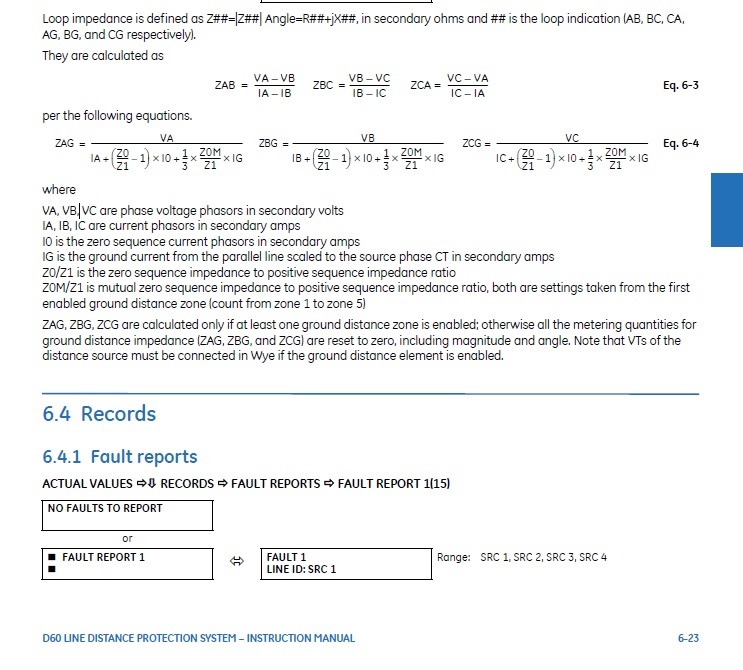
The relay trips on the equation for Zground. If you choose k to be very large for some reason, the impedance will be very sensitive to zero sequence current So, yes the impedance that you set the relay to trip needs to take k0M and K0 into account but Z2G normally should be close to Z2P with the same reach. If you are trying to figure out what the apparent impedance the relay sees due to infeed, plug VA, IA, and I0 into the equation.

D60_GROUND_DISTANCE_fprgdz.jpg
 
Hi marks1080,

The ground reach settings you enter are
in positive sequence secondary ohms. The
relay uses the z0/z1 value to calculate
the z1 impedance between relay and fault,
which is then compared to the ground reach
setting.

It isn't actually possible to apply the
residual compensation as you describe,
because the degree of adjustment depends
on the ground current. The relay only
knows the ground current when the fault
occurs.

I'd suggest once you finish your setting
work - simulate faults of different types
in CAPE and inject the calculated currents
and voltages into the relay. Check that the
relay does what you expect for faults near
the source bus, near the reach point, etc.

It's a very educational thing to do.

Also, note that in the D60 you enter the
ground reach for the quad elements as an
impedance at the line angle, which is both
odd and annoying. For most civilised relays
you just enter the reactance value.


Thanks,
Alan


As far as I know, the vast majority of line relays sold in North America have the ground quad "X" reach parallel to the line angle. That plus properly set k0 values mean that X can be set to the same value as the phase mho reaches.
 
Hi David,

Thanks for the comment - I've always
wondered why GE did that. We stopped
using mhos for phase distance years
ago, and from a quad/quad perspective
the input format seems strange.

Thanks,
Alan

 
Thanks for the replys! Most comments are inline with what I was thinking... I do admit, there is still some confusion on my part and I'm not sure if it's warranted, or if I am just missing something. Note: I'm using a MHO not a quad. Not sure if that makes a difference.

When I look in the manual for information (the 5.7x specific manual) I spend a lot of time looking at chapter 9.1 to understand exactly what the relay is doing internally. When I look at the formula for the direction ground MHO characteristics I see (using only A ground element for example):
A ground element: IA X Z + I_0 X K0 X Z + IG X K0M X Z - VA ANGLE compared with VA_1M ANGLE

This I more or less understand. The distance relay measures the angle (not the impedance, which i find is a common misconception of how the relay works) and then compares that angle with memorized voltage angle. If the angle is less than VA_1M, the fault must be internal.

In the application I'm working on I am ignoring K0M, which leaves me with:

IA X Z + I_0 X K0 X Z + IG - VA compared to VA_1M

I know that when we are looking setting ground reach, we want to do so based off of the positive sequence impedance. I'm not an expert here, but my understanding is that K0 (my zero sequence compensation) is what does exactly this. Therefore, if I have an impedance value from my fault software tool (CAPE in my case) I need to compensate this value which will end up giving me the positive sequence impedance. From the manual I can clearly see that K0 is being applied to my Z setting while the relay does its angle compare function. This is what is causing my confusion. I don't see why I should be applying K0 compensation to my impedance setting from my fault simulation software, when the relay is going to apply it during its compare calculations. My thinking is that I should be applying my ground reach setting without any zero sequence compensation to the impedance value, and let the relay apply K0 all by itself. It seems to me that if I apply a K0 factor to my reach setting prior to setting the relay, I am actually going to do a double compensation because the relay also does a K0 multiplication on the fly, while checking the angles. I will end up with K02 compensation, as opposed to just K0 compensation.

Am I misunderstanding what is going on here? I'm going under the assumption that the 'Z' in the formula above is the Z reach setting we define.

Whenever I get the chance I would like to check everything by importing my settings into CAPE vs. a bench test injecting real values into a D60 to see if things match up. I just haven't had the chance to do so yet.

Thanks again for the insight,
Mark
 
Hi Mark,

Your understanding is correct. The Z in the
equation you quote is the reach you enter in
to the relay, expressed as a vector.

The K0 in the equation is the relay applying
compensation to the measured current and voltage before comparing with the setting
(Z) in positive sequence ohms.

As an aside, I don't really understand why
anyone would use a mho characteristic with
a modern relay. Mhos made sense in an era
of electromechanical comparitors. The resistive coverage of a mho near the reach
point is horrendous - especially for short
lines. It's time for protection engineers to
enter the early 90s :)

Thanks,
Alan
 
Thanks Alan.

Couldn't agree more. It's not my choice to use mho. I could tell you about 1980s tech we still use but that's a different topic.

So you agree that the ground reach zone 2 impedance based on my Zapp max from my fault study should not be multiplied by a K0 factor when entering the setting?
 
Never used a GE relay, but with the Schweitzer relay, a proper k0 setting means that the ground reaches are set very similar (numerically) to the phase reaches. If the GE relays are different that's all the more reason not to use the GE relays.
 
Submonkey,

Enter the 90s? I think you are giving a lot of very conservative utilities too much credit. Quad mho, load encroachment, and ground distance is new to some. And as slick as 61850 is, I doubt I will see it adopted by many in my lifetime.
 
The 90s eh? I'd be happy to be rid of the 50s or 60s and the end of the KD and HZ relays. Our standard for new installations is a relay that could do phase quads, but I haven't seen any reason to switch from phase mhos. Ground, on the other hand, has been quad as long as we've been doing ground distance. I've never seen an event where a phase mho didn't have enough resistance coverage. Ground faults can need all the resistance coverage a quad can provide (and more), but phase-phase faults are all, in my experience, pretty low resistance. To date the phase mho has never let me down, no reason to look for the solution to a nonexistent problem. Anything short uses POTT or line differential and zone 1 mho reach is somewhat of a nonissue.

61850 is very definitely a solution in search of a problem. I'm just not seeing anything in my day-to-day work where I wish I had an additional tool. I'm not sure how 61850 is supposed to improve my life. Maybe if SIS wire were 10 or 20 times as expensive as it is, but certainly not today. Someday, maybe, it can replace the copper wire from the instrument transformers to the relays with fiber, but if we still have to run copper DC circuits to the breakers it won't allow me to fiber isolate the control house from the yard.

Change is great, I've driven a considerable amount of it, but it has to be change for a reason. Phase quads and 61850 would simply be change for the sake of change. Not going there.
 
One utility that I know of is digging into 61850 not to save money on copper but to be able to recommission a substation quicker after a disaster. Sort of like how Foundation Fieldbus, Profibus, and the other industrial bus protocols sell themselves on money made due to quicker plant start up.
 
Thanks everyone for the insight! It was very much appreciated.

I think there might be value in starting another thread to discuss line settings specifically. I agree with the posts in this forum, in general, but I believe it's very important not to use general rules of thumb when doing line settings. Ground reach could be drastically different from phase reach, depending on system variables, most significantly apparent impedance.

It's always nice to get confirmation on your methods with other people in the same industry but working in different regions.

The Mho Quad debate isn't really a debate anymore, imo. Quad is better. Funny to say, because I still use Mho where I work. I am fairly confident to say that Mho is still totally adequate in most situations.

@davidbeach: The discussion around IEDs vs Electro Mech relays is really coming full circle in my area. It has been suggested several times that perhaps we go back to having one of our A or B schemes be electromechanical again! Of course when the industry moved to IEDs large scale the industry also discovered a whole new set of issues specific to IEDs which was never important to consider in the electro mech world. Specifically, I'm talking about things like equipment grounding, input impedance and secondary burden. In my opinion, I love when situations like this happen because it means there will be another day/month/year before robots take my job from me!
 
Status
Not open for further replies.

Part and Inventory Search

Sponsor