Eng-Tips is the largest engineering community on the Internet

Intelligent Work Forums for Engineering Professionals

  • Congratulations waross on being selected by the Eng-Tips community for having the most helpful posts in the forums last week. Way to Go!

Gearing help 1

Status
Not open for further replies.

MrAtkinson

Mechanical
Jul 4, 2019
8
GB
Hi all,

I wanted to ask if an idea i have had is possible/if its the best way to do it. I am looking to push a panel which will weigh around 125lb to a specific distance (around 100mm) and then rotate the panel from the bottom corner 90 degrees up. I was originally thinking of having a linear actuator to push the panel out using a part geared shaft/spur gear, part round bar (i will call it the axle) and then have a Nema 34 motor with gears mounted to turn the shaft and rotate the panel.

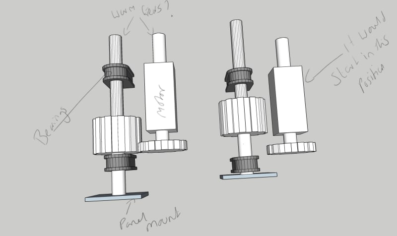
I then thought, would it be possible to eliminate the linear actuator and use a dual shaft nema motor. One end of the motor shaft has the gear to make the rotation but utilising a worm gear on the other end to push the axle forward. So essentially the motor spins the front gear and the worm gear at the same time, the worm gear pushes the axle forward to push the panel out 100mm but at a specific point of the linear motion of the axle the section of the axle that has the accepting gear interlocks with the gear on the other end of the motor and rotates which in turn rotates the panel.

I have created a very quick 3d model to give an idea of what I'm thinking of, nothing is to scale, its simply for visual reference. I've also attached the .skp file of the model in case its helpful.

I am self taught in this stuff so please bear with me if I have missed something obvious or over engineered it.

My questions are, would this be a viable way to do it? would I be able to get the worm gear to work with the shaft in parallel or would using a 90degree gear change be a better solution? OR does anyone know of a better way to do it?

Thanks

Jake
[URL unfurl="true"]https://res.cloudinary.com/engineering-com/raw/upload/v1641418435/tips/HInge_nqmw5o.skp[/url]
InkedIdea_one_LI_ruqofe.jpg
 
Replies continue below

Recommended for you

MrAtkinson,

There are some very high pitch lead screws out there. One of these may do your correct rotation and turn. Try Google.

--
JHG
 
@drawoh

I have considered using lead screws as well as ball screw however it will only really work to push the panel and not rotate.

@jboggs

Thanks for this I will check them out. I haven't done too much with regards to force etc yet as I want to get the base design right before I look at power/torque/force requirements and specific part specifications. My biggest question really is the best way to transfer the rotation from the back of the motor to the axle to move it forward. I have looked into worm gearing and not sure if it can be done in parallel with each other, i see worm gears mainly as changing a direction as in 90 degree from the motor axle not running parallel with each other. Im thinking that as long as the orientation of the threads are right it should work?
 
You could get much better advice if you told us clearly what you need to do instead of how you think it could be done.
 
@mintjulep

Hi, i explained what i need to do in the first paragraph of my initial post.

“I am looking to push a panel which will weigh around 125lb to a specific distance (around 100mm) and then rotate the panel from the bottom corner 90 degrees up.“

I have a couple of ideas about how to do it but wanted to get advice on whether i can use a worm type gear or if a 90degree gear change would be better. Id prefer to use a worm type gear if possible.

Thanks

Jake
 
When I asked about force and torque analysis, I was referring to the job itself, not the method you use. For example, how much force will be required to push your 125 lb load? Is it sliding on a supporting surface or is it supported by your device? Is friction a factor? You want to rotate the load about a lower corner but you don't tell us how far that corner is from the center of gravity. That will tell you how much torque is required for that action, no matter what method you use. Trying to select your mechanism before you know these factors is like getting the cart in front of the horse.
 

On the lead screw idea...The plate would be fixed to the lead screw and rotate with it. The pillow block bearings would have to be replaced with something keyed/nut.

Does the plat have to just spin 90? Or does it need to just end at 90? IE - attach to a screw and let it spin forward 100mm and stop it at a 90 turn.

I think what Drawoh was referring to is a 400mm pitch lead screw. Applying a 1/4 turn would advance it forward 100mm and turn it 90. Lotsa torque on that motor and odd lead screw makes me think that would be difficult to source.

The worm screw/big gear has capability but you may end with an annoyance trying to get it timed right. If one of them is offset from the other the motion could be erratic in alternating between the backlash of each gear. IE: Catches on the worm and drives forward, catches on the big gear and releases on the worm to rotate, catches on the worm... Eventually they will wear each other down till they match but then the whole assembly will have a lot of slop.

Is this a one off or production? If it's one off - a linear actuator + gear is probably safer. If it's production and the unit cost low then build one to see how it works. Maybe gear slop is less of an issue than anticipated.
 
Hello,

Can you draw a sketch of the path of the door itself?

I was looking at this video during lunch that might provide some brainstorming ideas depending on what you want to do with the door:


Maybe something like what is shown at the 18:45 mark.
 
@kjoiner

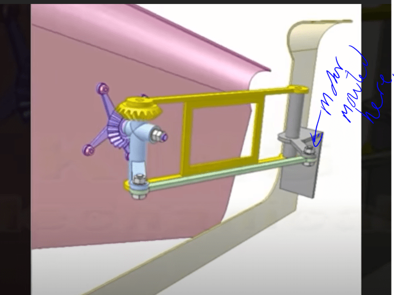
The scissor car door (06:00 mark) is the exact movement I'm looking to create!! The door panel is around 800mm wide and will weigh around 125lb. Looks like this is a much smoother and simpler way to accomplish what i'm trying to do. If i mounted the motor above the pivot point marked on the image below would that be the best place or would there be a better place?

Thank you for finding this.

Its also a one off project

door_hinge_taykrq.png
 
Hello,

Glad to help. Two thoughts:

1. The closer to the CG you can mount the pivot (the purple part mounted on the door) , the less lifting load (torque, moment etc.) you will need to account for.
2. I think the better location for the motor is on the yellow arm rather than the green link arm.
3. If a scissor door is what you want, take a look at some of the automotive solutions that have been used over the years for additional ideas.
 
MrAtkinson said:
The scissor car door (06:00 mark) is the exact movement I'm looking to create!!

That motion is quite different from your original description.

“I am looking to push a panel which will weigh around 125lb to a specific distance (around 100mm) and then rotate the panel from the bottom corner 90 degrees up.“

The correct drive point is the pivot of the yellow link, at the car frame end.
 
Status
Not open for further replies.

Part and Inventory Search

Sponsor

Back
Top