Eng-Tips is the largest engineering community on the Internet

Intelligent Work Forums for Engineering Professionals

  • Congratulations waross on being selected by the Tek-Tips community for having the most helpful posts in the forums last week. Way to Go!

General pumping questions

Status
Not open for further replies.

DiamondDave

Mechanical
Jan 27, 2009
51
0
0
GB
Hi guys,

I work at a dry dock facility and its bothering me that I dont know as much about our pumps as id like and I also have questions about our set up.

Should all pumps have a gauge on suction and discharge side and if so how do I read the information on them? What can it tell me?

Is there tests and data I should gather and make note off to later use to diagnose faults? Such as time to pump a certain level of water out of a dock?

Will the tide level pumps are pumping against make a difference to pump times?

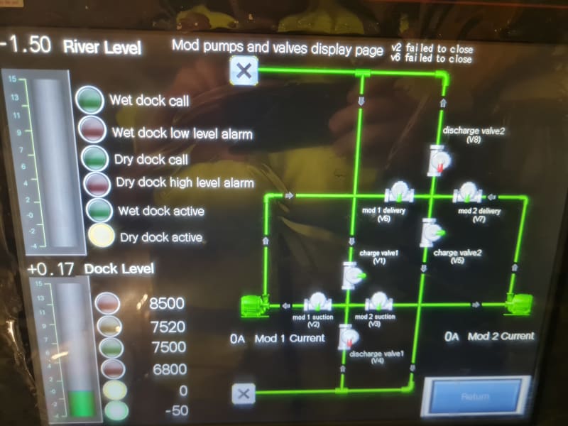
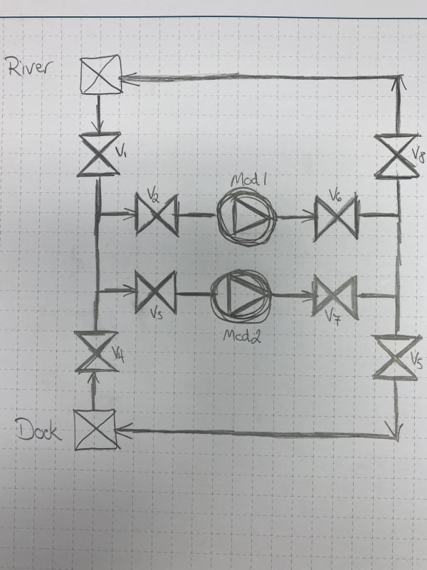
Regarding the schematic attached is it better to have 2 pumps running or just one? Will 2 pumps reduce discharge time or will they fight against each other and end up worse?


I am sure I will have more questions! Thanks in advance

 
 https://files.engineering.com/getfile.aspx?folder=e0144c8e-3987-4d95-99c1-dbdab0c35afd&file=20220817_081720.jpg
Replies continue below

Recommended for you

If the pumps are discharging end to end like it is shown on the diagram, it will just fight each other.

But maybe installation in the field is different and they are actually in parallel discharging to a common header. In this case, then you would increase flow rate. Now, be careful as if the pipe size was designed to a master+backup pump scenario, by putting both pumps running you might go over the pipe admissible pressure..
 
MedicineEng

Thanks for responding.

It actually looks like they discharge into a t-piece, 9ne from bottom one from the side to the discharge.

Coupd you explain to me how pressure works in a pump? Does it g up or down with flow rate?

There is also a lot of vibration within th3 pumps and pipework which is causing me concern, also the bolts on the flanges are only with an ordinary nut, no washers or anything is that normal?

I am embarassed to be asking these but its never actually been explained to me.
 
20220817_081720_quea2y.jpg


How is it that discharge valve 1 appears to be in the pump suction?

Perhaps you should verify if those are cross fittings or the pipe simply cross over each other without connecting. I can't see any difference in that photo. Can you make a schematic, so we don't have to guess what's going on.

Is this supposed to be able to pump from one of the Xs to the other X1 to X2, then turn it around and pump form X2 to X1? Please explain what you are trying to accomplish, or what this system is supposed to do.

With a free flowing pump, Generally You get highest pump discharge pressure when pump flow rate is low. Pressure decreases as pump flow rate increases. Obviously with a closed discharge valve, pump pressure will always be high. With a full open discharge valve, flow may be high, but pressure low, so you can see that pressure and flow depend on the pump AND the system in which it is installed.

How the tide affects the pumps depends on if you are drawing from the ocean, or discharging (below tide level) into it.
A rising tide on discharge will slow the pump flows. A rising tide on suction will tend to increase flow. Pressure may increase with both. A falling g tide will generally do the opposite.

Two (similar) pumps with a common suction and a common discharge do not fight each other. Their flow rates add together, while discharge pressures tend to remain equal.

Two (similar) pumps configured P1 discharge to P2 suction generally keep the same flow rate, however discharge pressure of P2 will be the sum of the suction at P1 plus the two pumps differential pressure.

Einstein gave the same test to students every year. When asked why he would do something like that, "Because the answers had changed."
 
1503-44, thanks for replying

So the discharge valves should be open when the dock is being discharged "pumped out" and the charge valves should be open if the dock is being charged (wanted pumped in) the cross fitting after discharge valve 1 is connected to all those pipes as is the cross fitting after discharge valve 2 every other cross point is just pipes running past each other not connected. You can open the charge valves and discharge valves and by pass the pumps and have water pass directly into the dock or out of the dock depending on river and dock levels.

The top X represents a manually controlled valve on the river side of the system and the bottom x represents a manually controlled valve on the dock side. Both are usually open. So yes the system is supposed to pump in either direction.

Thank you for the information, so would I be right in suggesting that as these pumps come from a common point at X and eventually deliver through another common point they will not fight each other and in fact assist? Is there any reason why you think they should not be on at the same time?


DiamondDave,
I took the liberty of redrawing your piping into a little more straightforward process layout which might be easier to follow. Please take a look and check the logic, but I think I followed the photo, just splitting the crosses into headers to allow rearraging the layout. I'll comment again when time permits to go into a bit more detail and some pumping basics, unless someone else beats me to it.

IMG_4226_iu1nto.jpg
 
Hey there Rputvin, thanks for that schematic. That makes it a lot easier.

I assume that the schematic is correct and those are identical pumps.
With info given, minimal, I don't see any reason that you could not run 1 or both pumps. With identical pumps you will get more or less twice the flow as running one and the discharge pressure will be about the same if you run one or two pumps. It could be a little less flow than 2X and a little less pressure, because flow resistance increases at 2X the flow. If you have small diameter pipe, that could be a lot more resistance, causing a marked decrease in both flow and pressure.

With high tide, pump discharge pressure will rise a bit as well. At Low tide it will fall.

If you start closing V5, flow will decrease and pump discharge pressure will rise to maximum.
When V5 is fully open, flow will be at max and pump discharge pressure will be at minimum.

I need pipe diameters, lengths, high and low tide marks and Dock levels and of course the pump curves to be more specific.

A pressure gage at pump discharges will enable you to see what the discharge pressure is at any given time, confirming that your pump is producing the correct discharge pressure for the conditions present. You could check that against the pump curve and do some simple calculations to confirm all is OK. without those, you're kind of flying blind, but in a system that simple and some operating experience, you might not really need them.

A suction pressure gage could probably tell you if you are taking in the proper amount of water.
Subtracting suction pressure from discharge pressure will tell you how much head, or pressure the pump is adding to suction pressure and once again, it could confirm that the pump is operating properly and could give you an estimate of the flow rate in the pump, plus make other diagnostic calculations, such as its power consumption.

Can't say too much more without all the details mentioned previously.

Einstein gave the same test to students every year. When asked why he would do something like that, "Because the answers had changed."
 
I was editing at the same time, so re-read some of the last to make sure you've seen all.

Einstein gave the same test to students every year. When asked why he would do something like that, "Because the answers had changed."
 
Thanks.


I was away from site when all this was installed but I am supposed to operate and maintain it but I havent seen a manual for any of it.

Im also conscious that we have never been trained on understanding gauages and what head means etc or how to calculate pressure differentials and what they mean or how to read and interpret pump curves. I feel all this info would be good so I know when the pumps are running as they should be or when we are pushing them too hard. Im taking this all on myself to learn.

Its a simple system but it is critical as failure could be costly if ships are in docks etc.

I will trt and get more information.

Pipe diamter is 12" IIRC the dock level can be pumped up to a maximum of 10m or 33 feet. The river tide varies obviously but I reckon doesnt go higher than 8m or lower than 5. Right now I am trying to get the water right out the dock, but may have encountered other problems due to design change which stops us getting it completely dry vlbefore the pumps draw air and lose their prime.

I have actually had both pumps running as we used to do it that way before everything was overhauled and flow did seem to improve, but id like to back up anything with facts and figures.

So am i correct in drawing from what you say that both pumps going into a t piece into a common outlet wont fight each other?


We are getting a lot of vibration in the system but the set up hardly has any straight sections its all very condensed with lots of tpieces and elbows. Could this be contributing along with a low suction head?

 
If the pumps were VFD controlled to each deliver a different flow rate, then they would produce different discharge pressures; then some fighting might start happening. Two similar pumps running at constant speed won't fight. They basically just add both their flows together.

Actually it's not the pumps that fight, it's the controls. No controls, no battles. Pumps just try to do what they're told.

Einstein gave the same test to students every year. When asked why he would do something like that, "Because the answers had changed."
 
Dave,
Do you have copies of the pump curves, or information on the pump so we can get electronic copies of the curves?

This will be easier to explain your system and pumps, vs. trying to give you a crash course in pump performance theory.

Using 12" pipe your pumps will be fine up to about 3000 GPM combined flow before you'll need to worry about velocity, pressure drop, system resistance for 1-or-2 pumps running and fighting each other, or anything else from the pipe on either the suction or discharge side of the pumps. But we don't know if that's beyond your pumps' capacity, or if you're flowing well beyond that and all your pipes are getting hammered like crazy as a result.
 
Thank you very much for responding guys.

I am going to try and get a manual tomorrow, ill also confirm pipe diameters and get what informatjon I can from the pump tally plates.

Off the top of my head they are gorman rupp super t-series 10" ive actually just found their website and they have manuals available and performance curves, i cant post the links unfortunately


The pumps dont have any speed controls I am aware of, they are on or off. Ill also try to find out why this apparent restriction on only running one is in place.


Dave,

Looking at the OP and responses it looks good to me.

Those pumps are slightly oddball as they seem to be self priming pumps. These allow the pumps to be placed above the liquid level at the start of operation and lift water into the pump to be able to operate. not many centrifugal pumps do this.

Now once primed, the pump can now operate below atmospheric pressure at the inlet which is why a pressure guage able measure down to -1 barg would be useful. How much below atmospheric is defined in part by the NPSH of the pump which varies by flow. Many people mistakenly believe that NPSH is the ability of the pump to "lift" water without the pump cavitating. This is not correct. My suspicion from reading your posts is that the vibration and shaking and inability to clear the lower lines may be because your pumps are cavitating, so knowing what the inlet pressure is, especially below atmospheric, is essential.

Now in terms of getting to know your pumps, try looking at
The second main point is get to know and love your pump curves of your particular pump.

Remember that the head is differential head between inlet and outlet (hence guages are very useful) and that the duty point is simply some point picked by the designer to satisfy some design flow. Your inlet and outlet head keeps changing due to level in dry dock and tidal level so you won't have a fixed flow but probably start at somewhere on the right hand end and move slowly to the left of the curve. Now another possibility for vibration etc is that pump, at least at initial conditions, is operating beyond what's called "end of curve" as there is only frictional losses in the pipe as the dry dock and river level are the same, but then this changes over time as you pump out the dock and the tide rises. Pump flow can increase and decrease without the pump changing speed. It can be a bit difficult to get your head around, but for centrifugal pumps that's how it works.

It might be that at the start it's better to run both pumps at the same time to bring the pumps back onto the curve as flow will increase ( almost certainly not double), but this will increase the frictional losses, but then as the flow reduces, you don't actually suffer much if you only run one pump.

It's also very useful to know flowrate and also motor power (volts / current etc).

Long term you should be able to monitor any drop off in flow for the same differential head or monitor efficiency reduction. in very simplistic terms Power out is head times flow for the fluid and power in is volts x amps. Reduction in flow for the same DP or reduction in efficiency should result in pump inspection and strip down.


Remember - More details = better answers
Also: If you get a response it's polite to respond to it.
 
Hi littleinch,thanks for an informative post.

Ive taken some more measurements. Id say the centre of the pumps are approximately 13 feet from the dock floor which is 0 on the draftboard but we have a dock sump where the pumps draw from which was full and is probably another 10 feet deeper than the dock floor.

The pumps were running at 73 amps which i am told means they are pumping. I feel thogh there is an over reliance on electrical indications and not enough "mechanical" feed back such as pressures, heads, heights, flows etc. I feel as if whoever had designed it has dismissed them as unimportant or not been aware of them.


These pumps are indeed self priming, our old ones had a vacuum tank, this system is still used for the main de watering pumps which are considerably larger in diameter. I have actually been trying to get one of them started using the priming system and a throttled delivery valve but i cannot get them to prime. The tank is showing 25inHG on its gauge but I think the top hat on the pump is blocked as there is no water in the pump casing. Do you think 25inHG should be enough to prime a system if the water level is approximately 10 feet lower than pump casing?


Id like to recommend that we fit gauges to all suction and discharge sides of pumps, is this someting you chaps would recommend?
 
No problem.

A 13ft / 4m lift should be within the capability of the pump.

You would need to look at the pump curve and see where 73 amps get you once you allow for the motor efficiency / power factor. Remember the power in the pump curve is shaft power, not motor inlet electrical power.

Normally for priming you would isolate the discharge on the pump and draw water into the casing with a non return or "foot valve" on the inlet into the pump before starting the pump. But 25 inches HG should draw up about 8m / 25ft of water. Your pump might not like 8m of lift though.

But yes, putting guages on and being able to measure flow in some form is usually a good thing as it lets you know where on the curve you are sitting and allow you to troubleshoot much better.

Oh and stud bolts and nuts without washers is common for me, but I appreciate others like them. Works in either case.


Remember - More details = better answers
Also: If you get a response it's polite to respond to it.
 
Hi,
I agree with all the comments above but if I was in your shoes I will contact a third party to come and measure the flowrate (s) in different configuration using a non intrusive , portable flowmeter , let say Doppler effect technology or ultrasonic , or I will purchase one to follow up the performance of my pumping system .
Note : definitely good to have gauges installed at the discharge of the pumps , same for amps meters .


My 2 cents
Pierre
 
Thank you again guys.

I was getting 25inHG on the vacuum tank gauge but the pumo casing was empty, it didnt even look as if tried to pump. I had also throttled the valve so to try and prevent it discharging everything too quickly.

I am convinced there is a blockage in the priming system as it went to 25inHG fsr too quickly in my view.

The pumps should have "only" been trying to lift 15 feet or so once primed.

This is only on our big pumps however.

On the small pumps I need to double check what their priming distance is in the manual as modifications to the dock.may have taken it out of spec, either that or the inlet pipe is exposed to air before the dock sonar pit is dry.


Going forward im going to recommend gauges on on pumps, and try to get a more thorough maintenance schedule.put in place. Ill look into suggesting some kind of flow meter be installed.

Im going to try and mess about with calcuations to see what our pumps are theoretically capable of and how far out of that we are trying to pump.

Just the usual mushroom treatment.

I honestly feel like we can never have enough information but we get very little.
 
What's the thing on top of the pump to stop water getting into the vacuum system?

Usually has some sort of a float in it and they are a bit notorious for getting blocked / silted up / corroded. A good place to start.

The level of misunderstanding about how pump systems work is unbelievably high.

Vast majority of the time on these forums we find out there is nothing wrong with the pump, just that the design or operation is poor.

Remember - More details = better answers
Also: If you get a response it's polite to respond to it.
 
Thats actually my thoughts, i think its a sping loaded needle valve weighed down will a ball cock that should float once primed and close the pipework to stop water getting drawn in and thus giving the signal to start the pumps. I suspect either the valve is seized or the chain holding the ball has burst allowing the valve to shut giving the illusion of 25inHG. Its slightly different to ones ive worked on before but i assume its a set up like this.

Ill find out once i get it open anyway.

I think the pumps are decent to be fair, our big pumps are almost 100 year old drysdale pumps. Amazing machines.
 
Status
Not open for further replies.
Back
Top