Continue to Site

Eng-Tips is the largest engineering community on the Internet

Intelligent Work Forums for Engineering Professionals

  • Congratulations KootK on being selected by the Eng-Tips community for having the most helpful posts in the forums last week. Way to Go!

Generative Struct Analysis Assembly Modeling Connections

Status
Not open for further replies.

CPosner

Mechanical
Jan 26, 2007
139
I need some suggestions on how to model an assembly.

I have simplified what I am modeling in the picture below. There is a Hexagonal shaft placed into a female hexagonal base. There is a small amount of clearance between the two parts radially speaking(no initial radial contact). The shafft end contacts the bottom o the base. Let's assume there is a small screw or spring holding the base to the end of the shaft.

Initial conditions..the base is fully fixed and there is a small torque on the shaft's main axis and also a load applied normal to the highlighted surface.

How can I generate the FE model. I used the contact constraint, but my assembly has no constraints which limit rotation of the parts because there is the clearance between the two. In actuality, there will be contact between the hexagonal surfaces, once loads are applied. Also, I thought about using the spring connection between the base and the shaft to help keep the parts together. I have gotten results some results, but I am not 100% confident in the FE model.

Any tips on the assembly or what type of conenctions to use would be appreciated. Thanks!
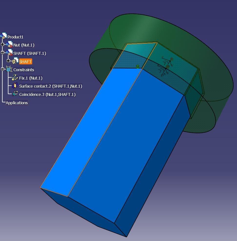
shaftnut.jpg
 
Replies continue below

Recommended for you

Hello,

I am not FEA guru but CATIA does linear analysis only.

If there is no contact condition in the initial state, then is it a non linear analysis ?

Eric N.
indocti discant et ament meminisse periti
 
CPosner,

I have done the same thing as you did. I've clamped the base. I put a general connection + slider property between the base and the shaft. That way, it prevents the shaft to move along its axis without preventing the shaft to turn around it.

Then, I put 6 contacts between the six faces of the shaft and the corresponding faces of the base. My model has a clearance of 0.05in. In my case, the shaft always enter in contact with the base so there is no rigid body motion.

I put a virtual rigid element at the other hand of the shaft on which I applied a torque.

I think this should be a good way to model all this. I have attached here a .doc file in which I show you a little bit how I modeled it as well as the Von Mises Stresses I got, which look logical. I didn't made any hand calculation check though, but should at least be a good approximation.
 
 http://files.engineering.com/getfile.aspx?folder=48dd46d3-7b27-481f-a846-04e0edb47f61&file=CatiaV5_study_engtips.doc
itsmyjob,
I think you are correct, but I think it can simulated with a Linear analysis.

francoislambert11,

Thanks for that Document, that was helpful. How were you able to make the 6 contacts between the base and shaft?

I think that the slider connection between the shaft end and the base may not be correct cause that always keep those two surfaces parallel. In reality think that that may not be the case. I have attached a sketch describing what I think would happen. The shaft end may loose contact with the base at some location.

I tried to use a spring contact connection and a spring with stiffness along the axial direction to model that. Those 6 contacts I am still confused as how to create those.

Thanks,
C

 
1- itsmyjob is correct, it is linear contact, not non-linear contact as MSC Nastran Sol600 can do. What it actually means, I'm not really sure. I think, and this is my asumption, is that in linear contact, one contact does not influence another.

In reality, when there is a contact, the deformation of the part might change and cause a new contact elsewhere that wouldn't happen without the first contact. That second contact, Catia won't see it, but Nastran Sol 600 will. Still this is my assumption.

2 - You are right about you drafting. I was assuming that you would apply a pure torque load around the axis of the shaft, which shouldn't cause the situation in your drawings. Anyhow, you are probably right by doing a spring connection between the base and the shaft with a very low stiffness (10 lb/in) in the shaft axis direction. That way, it prevents the shaft from having a rigid body motion along this axis. But you wont have the contact effect between the base and the shaft. So I would try
to do exactly this, but adding a contact between the tip of the shaft and the bottom of the base (where I put a slider before). It should work and if there is a contact at this location, Catia might see it... or not as previously discussed, but since you apply a force and not a torque, i think it will.

3 - For the six contacts. I made 6 general analysis connections with GAS, one per face facing each other (represented in the first picture by the long greenlines). Then I defined 6 contact properties, one for each analysis connection (represented by the little black boxes in the second picture). I put initial clearance 0in.

Hope this helps.


Status
Not open for further replies.

Part and Inventory Search

Sponsor