Eng-Tips is the largest engineering community on the Internet

Intelligent Work Forums for Engineering Professionals

  • Congratulations waross on being selected by the Tek-Tips community for having the most helpful posts in the forums last week. Way to Go!

Generator and AVR types 1

Status
Not open for further replies.

sbkenn

Mechanical
Feb 22, 2010
64
0
0
IE
Hi. I am looking for an AVR for a 3-phase brushed alternator/generator. Are AVRs for brushless units similar, just without the rectifier ? If I added a rectifier to a brushless type, would it work with a brushed system ? What is the difference between an AVR for a single-phase and a 3-phase system ?
With the generator that I have, when it starts generating, it draws quite a bit of power just for the excitation. I am suspicious that there is insulation breakdown in the rotor resulting in suppressed flux/amp. Does that make sense ?
TIA
 
Replies continue below

Recommended for you

Typically, an AVR can work on all types of generator sets. 1 or 3 phase, slip ring or brushless, PMG, low and high voltage, etc...

However, your AVR must be compatible with your field current and field resistance requirements. In my small applications I have seen field resistance range from 5 ohm to 50 ohm. Regulators range from 3 amp to 12 amp output.

This website has tons of good information:
If your unit is brushless and excitation current is high, it sounds as if you have a diode failing shorted on the rectifier ring.

 
A bit more (ok a lot more) info would be helpful to give you a good recommendation. My go to source for brush type generator AVR's is Power-Tronincs, they have a large line of AVR systems and excellent technical support.

The field power requirements between brush type and brushless generators can be quite large.

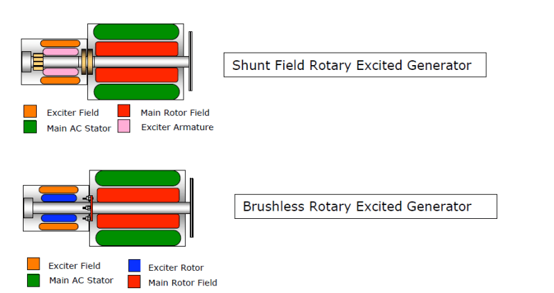
Here is a simple set of descriptions of many generator types,
When you say "draws quite a bit of power", do you know what your rated field amps are supposed to be?

More details will get you better answers, hope that helps,

MikeL.
 
Some old exciter type sets were converted to brushless and ran with the same AVR.
The toughest part of the conversion may have been cutting a key-way or groove in the shaft, past the back end bearing so that three wires could be passed from the exciter towards the field.
In some generator designs the bearing was outboard of the exciter and the conversion was easier.
An aluminum plate would be fastened to rotate with the shaft and the three phase bridge diodes would be mounted on the plate.
From a theoretical perspective, three phase power could be tapped from three commutator segments space at 120 degrees.
In practice that would be at the wrong end of the armature.
The commutator would be removed.
The armature could be rewound with a similar winding with no taps for commutator segments but three 120 degree taps at the opposite end of the armature.
A PMG set takes a special AVR, however in the event of the failure of either the PMG or the PMG AVR, a generic AVR, powered from one or two phases may be used until spare parts arrive. You will lose the PMG advantages until the PMG system is restored.

Single phase and three phase AVRs:
This may apply to the AVR power or the AVR sensing.
Generators have fairly wide phase voltage drops with uneven phase loading.
Most AVRs use single phase sensing.
Phase to neutral sensing may be used for three phase, but phase to phase sensing is better for unbalanced loads.
Some AVRs use three phase sensing but it is often pointless. The AVR cannot correct voltage differences due to unequal loading.
Phase to phase sensing works the best when combined with local knowledge and judgement as to which to phases to pick the sense voltage from depending on which phases are likely to experience the greatest loading.

The bottom line a generic AVR using single phase power and sensing phase to phase will get most smaller, stand alone gen sets operating acceptably. We had a lineup of 5 diesel gen-sets, a mix of 600 KW and 350 KW. They were paralleled as needed.
All ran well with generic AVRs with an added quadrature circuit. If an AVR lacks a quadrature circuit for sharing VARs in parallel operation, you can roll your own with one suitably sized resistor.
You can cut the quadrature resistor out of a failed AVR and use it with a generic AVR.
The only important thing is the field resistance as TugBoatEng mentioned.
Most generic AVRs will control most generators but you should check the AVR rating against the generator field resistance.
That is the resistance of the brushless exciter field, not the main generator field.
(Smaller: Up to around 1 MegaWatt or two MegaWatts.)

Bill
--------------------
Ohm's law
Not just a good idea;
It's the LAW!
 
WARNING POSSIBLE EXCEPTION.
Hi. I am looking for an AVR for a 3-phase brushed alternator/generator
There are three types of brushed generators.
1. Some have a stationary field. The power is taken off of the rotor with slip rings. This will have a special AVR, but I haven't seen one of these for years and it was very old then.
2. Some have a static exciter/AVR and slip rings to take the DC to the main field. These use a special static exciter and may have an internal AVR. I have only seen one of these, and the problem was with the governor setting, not the voltage control.
3. The most common type of excitation used a small DC exciter that was controlled by a generic AVR. The DC was taken from the generator by brushes and passed to the main field by slip rings. These are the sets that were often converted to brushless.

Bill
--------------------
Ohm's law
Not just a good idea;
It's the LAW!
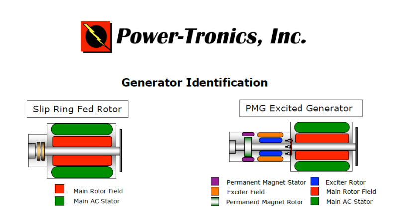
 
That's a great link, Mike. Worth an lps.
From Mike's link, what I tried to describe, illustrated clearly.
image_wj9f7k.png

image_drdz3m.png

image_xomicw.png


Bill
--------------------
Ohm's law
Not just a good idea;
It's the LAW!
 
Hi guys, and thanks for the suggestions.. The generator is a "slip-ring fed rotor" rated at 15kVA, 230V 3-phase has only the 3 phases wound, plus the slip-ring fed rotor. Most AVRs that I have found use auxiliary windings (or are they just coupled chokes from the power circuit ?), through a rectifier, to feed the rotor, with the regulation being on the low-side of the rotor rings. I don't know if I can rectify or otherwise use the power circuit for that purpose.
 
The typical basic AVRs that many of us are familiar with will have:
Two power terminals, fed from the generator output.
Two sense terminals fed from the generator output.
Two DC output terminals to feed an exciter field.
Two terminals to select 50Hz or 60 Hz for the UFRO circuit.
On some economy models, the power in and sense may be combined.
As the AVR gets more complex, terminals may be added for a quadrature circuit for parallel operation.
A PMG may be added to the set and then power from the PMG will be fed to three terminals on the AVR.
catserveng said:
The field power requirements between brush type and brushless generators can be quite large.
Typically the AVR feeds the exciter field. If the AVR is feeding the main field, it needs a lot more capacity than the generic, off the shelf AVRs can handle.
Does your set have an exciter?
Pictures?

--------------------
Ohm's law
Not just a good idea;
It's the LAW!
 
Status
Not open for further replies.
Back
Top