Continue to Site

Eng-Tips is the largest engineering community on the Internet

Intelligent Work Forums for Engineering Professionals

  • Congratulations IDS on being selected by the Eng-Tips community for having the most helpful posts in the forums last week. Way to Go!

Generator voltage change 3

Status
Not open for further replies.

JORDAN1128

Military
Nov 28, 2017
1
I have a winco 225kw trailer mounted generator that is factory set for 120/208 voltage with a 900 amp breaker. My question is that I want to be able to use this generator for buildings that are 277/480. I want an easy way to pick either voltage depending on building I'm connecting to. I have some buildings that 120/208 and some that are 277/480. The generator is not designed with the switchable voltage feature that some come with. Would it be easy enough to maybe install a step up transformer that is fed into 600 amp breaker. I thought about rewiring the taps, but I don't want to have to do that every time i need to change. Any thoughts. Thanks
 
Replies continue below

Recommended for you

I think a 208/480V, 300kVA 3-phase transformer will be required. Generator that is designed for 208V cannot give 480V.
You can have a switching panel with transformer as suggested, wiring and a switch to switch between 208V and 480V outputs. 208V will be directly from the generator terminals and 480V through step-up transformer.
However, considering the large currents to be handled, it is not going to be easy.

Rompicherla Raghunath
 
You are a little off base there raghun.
Check a spec.
The standard generator in that size in North America will have six x 140+ Volt windings, two per phase..
For 120:208 Volts the phase windings are in parallel and the AVR is dialed down to 208 Volts phase to phase.
For 277:480 the phase windings are in series and the AVR is dialed up to 480 Volts, phase to phase.
For a do it yourself change over with mostly off the shelf parts:
225 kW = 281 KVA
281 KVA @ 208 Volts = 780 Amps
Each winding group will supply 390 amps.
Three 400 Amp breakers.
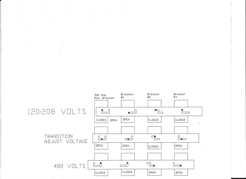
The breakers are mounted side by side and the existing 900 Amp . A sliding metal plate is mounted in front of the breaker covering the breaker handles.
Slots are cut in the plate for the breaker handles.
In the left most position the number 1 breaker is closed. The slots are such as to block the closing of the other two breakers when breaker number 1 is closed.
When breaker number one is opened, and the 900 Amp breaker is opened, the plate may be moved one position to the right. Now breaker number 1 is blocked open, the 900 Amp breaker is blocked open and breaker number 3 is still blocked open. Breaker number two may now be closed.
When breaker number two is closed, the plate may be moved to the last position on the right and breaker number 3 may be closed and the 900 Amp breaker may now be closed.
Connections.
Breaker #1 closed, 277:480 Volts.
Breaker number 1 connects T4-T7, T5-T8 and T6-T9.

Changing to 120:208 Volts
Breaker number 2 connects T4-T5-T6.
Breaker number 3 connects T1-T7, T2-T8 and T3-T9.
Adjust the AVR for the correct voltage before closing the 900 amp breaker.
The first few times, check the stability.
It's late and I'm tired. If I get a chance tomorrow I will draw a sketch of how the plate should look.

Bill
--------------------
"Why not the best?"
Jimmy Carter
 
Thanks Bill for correcting me. I learnt a new thing today.

Rompicherla Raghunath
 
Here is a sketch of what the sliding bar will look like. When the breakers are closed, they lock the bar in position. When selected breakers are opened, it is then possible to slide the bar sideways to a position that allows selected breakers to be closed.
This is an illustration with three positions.
In practice I would use 5 positions so that none of the switching breakers can be changed when the 900 Amp breaker is closed.
VOLTAGE_CHANGE01_vpudj5.jpg


Bill
--------------------
"Why not the best?"
Jimmy Carter
 
Voltage adjust:
If you connect a 250 Volt voltmeter across T7 and T8 of the generator leads, you may use it to adjust the voltage to 208 Volts for 120:208 Volt use, and to 240 Volts for 480 Volt use.

Bill
--------------------
"Why not the best?"
Jimmy Carter
 
Nice work waross. Over here I'm aware that alternators have different winding arrangements possible, I've just never had to deal with it, as we only really have one standard voltage arrangement in use.

EDMS Australia
 
Hi Freddy;
The vast majority of small generators here have two windings per phase with 12 leads brought out. (Smal, up to several MW)
The voltages available from a standard voltage are:
120:208 3 Ph Wye
139:240 3 Ph wye (Not common but sometimes seen in marine applications)
277:480 3 Ph wye
120:240 3 Ph 4 wire delta

120:240 1 Ph double delta
120:240 1 Ph zig zag
120:240 1 Ph bar diamond or Collin connection (Used for a single phase conversion of an old 10 lead gen-set)
120:208 2 phases used for pseudo single phase. One phase is abandoned.

The KVA and available kW change with some voltage changes.
eg: rated current per winding = 50 Amps
277:480 @ 50 Amps = 13850 VA x 3 Ph/1000 = 41.6 KVA, and 33.2 kW @ 80% Pf
120:208 @ 100 Amps = 1200 VA x 3 Ph/1000 = 36.0 KVA, and 28.8 kW @ 80% Pf (This set will safely produce 33.2 kW @ PF 87% at 120:208 Volts, however the convention is to rate the kW at 80% PF.

Bill
--------------------
"Why not the best?"
Jimmy Carter
 
Status
Not open for further replies.

Part and Inventory Search

Sponsor