Continue to Site

Eng-Tips is the largest engineering community on the Internet

Intelligent Work Forums for Engineering Professionals

  • Congratulations KootK on being selected by the Eng-Tips community for having the most helpful posts in the forums last week. Way to Go!

Geometry > Midsurfaces > Assign Mesh Attributes 4

Status
Not open for further replies.

Wnuczko

Mechanical
Jan 7, 2016
23
Hi there,

1. I'm using this function as in video here ( to automatically get surface thickness from my solid model.

But of course Femap is not always perfect. Can I correct the result somehow? I can't see any element proporties with different thickness or anything that might give me a clue how to.

Would be silly to implement function that when gives minor mistakes can't be accepted since cna't be corrected.

2. Second thing, when I apply mesh sizing on surface or solid - sometimes I directly see nodes position adjusting and changing, and sometimes there are not there. Only after remesh I see resulting size on build mesh. Is this typical bug?

Rgds,
Mateusz
 
Replies continue below

Recommended for you

the video showed you that as part of meshing you have to define the element property.

i'm not sure i like your explanation of what the video was showing ... "to automatically get surface thickness from my solid model" ... i'd express it as they're extracting a mid-surface representation for the solid so you can use 2D elements.

where i am we're lazy (and proud?) ... we just tet mesh the thing. so what if it takes 5 minutes to solve.

another day in paradise, or is paradise one day closer ?
 
Non an option for tet. Too heavy model, too weak machines.

I'm sorry. I will explain better my question. Please forget the mess above.

1. I have solid model.
2. I do midsurface extraction.
3. Before meshing I create default Properties with no thickness assigned inside - there is 0
4. I mesh it and see that the elements have thickness.


Question is: where can I see it and adjust the plate elements thickness if under Model > Properties I see only one Property with thickness 0 and on model view I see 3 different thicknesses?
In other words what is the best way to control plate elements thickness.

Rgds,
Mateusz
 
Dear Mateusz,
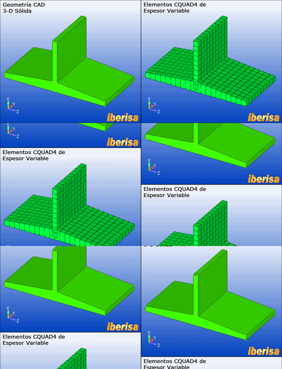
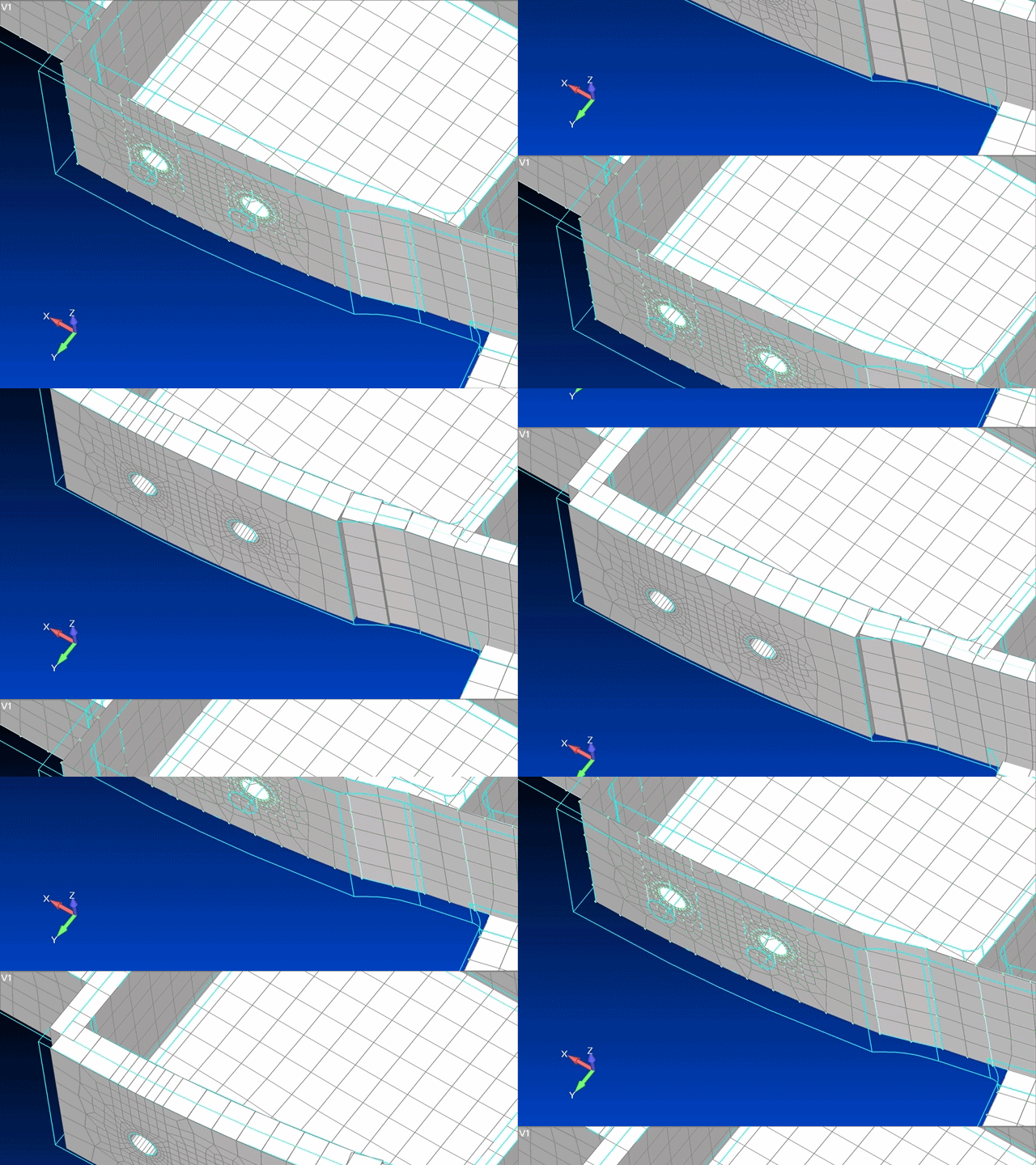
You can prescribe attributes on surfaces using command MESH > MESH CONTROL > ATTRIBUTES ON SURFACES, for 2-D shell CQUAD4 elementes this is the thickness & material properties. In your example the central thicker part will have different thickness, then you need to create a new property, etc... You can run this way, this is the classical aproach for shell meshing of midsurfaces, this is the way I do in general, but with FEMAP V11.2 you can also use the "magic" button to have only ONE property but many thickness & OFFSETs applied to the Shell mesh, great!!. This is the command "MODIFY > UPDATE ELEMENTS > MIDSURFACE THICKNESS AND OFFSET". This command attempts to update the element thickness and apply appropriate offsets for elements to better match the original solid used to create the midsurface(s).

variable-thickness-menu_ft9vxq.png


variable-thickness-animated.png_uhpzqg.gif


MidSurfaceThickness-Variable-Animated_pptshq.gif


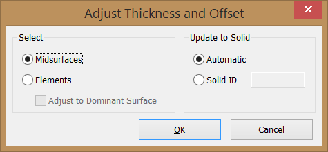
The Select section allows you to specify if you will be selecting Midsurfaces themselves, which will then automat­ically select the plate elements associated with those midsurfaces, or any number of plates Elements. When the Ele­ments is selected, there is an additional option to Adjust to Dominant Surface. When enabled, Adjust to Dominant Surface will adjust the element thickness and offsets of all selected elements based on the surface of each Solid used to determine the thickness and offsets for the largest number of selected elements.

The Update to Solid section allows you to select how the solids used to determine thickness and offsets will be selected. When set to Automatic, each misdurface or element will automatically determine which solid to use, while when set to Solid ID, you will need to specify the ID of a solid or select s solid from the graphics window.

Please feel free to post your FEMAP model here if you need to receive any help, thanks!.
Best regards,
Blas.

~~~~~~~~~~~~~~~~~~~~~~
Blas Molero Hidalgo
Ingeniero Industrial
Director

IBERISA
48004 BILBAO (SPAIN)
WEB: Blog de FEMAP & NX Nastran:
 
Blas, thanks a lot for your big reply!

But I stil can't do what I want. Let's start simple example.

1. I have drawn in femap a surface 100x100 on plane XY (Z=0)
2. In properties I say thickness is 10mm
3. Surface is meshed and the thickness is distributed equally: 5mm to -Z and 5mm to +Z.

I want to change the offset to have for example thickness going from Z= -2 to Z= +8.

Could somebody explain step by step, please.

Rgds,
Wnuczko
 
Hi Wnuczko,
you can modify the offset/thickness of your elements in

Modify --- Update Elements --- Adjust Plate Thickness/Offset...
 
Damn!!!

Double click to refresh! That what I was missing all the time :)

Thank you crostolo.
 
Status
Not open for further replies.

Part and Inventory Search

Sponsor