Continue to Site

Eng-Tips is the largest engineering community on the Internet

Intelligent Work Forums for Engineering Professionals

  • Congratulations SDETERS on being selected by the Eng-Tips community for having the most helpful posts in the forums last week. Way to Go!

Glue and Touch contact on the same SOL 101 analysis. 2

Status
Not open for further replies.

Emi.Cor

New member
Jun 24, 2022
8
Hello,

I am conducting a static analysis in which I have both glue and touch contacts.

My problem is to know how to actually define multiple contacts, and within it, the BCPARA entry where I define the LINCNT
paramater to 1 for the glue contact, but I cannot define another BCPARA card with LINCNT = 0 for the
touch contact. I read in the QRG that only one BCPARA card is admitted in the SOL 101 and that it must have ID = 0.
So, my problem is how to define many different contacts in the same analysis.

The first contact I did was the glue contact and it worked, and now I am adding the touch contact.
One additional question concerning the glued contacts is : Is it normal to not obtain contact outputs when working with glued contacts?
Because I have no outputs, even if I put as global output BOUTPUT = ALL.

Furthermore, when I run the analysis, it does not converge. And the .f06 file gives me this message :

*** USER WARNING MESSAGE 8156 (MCN1GCK)
GENERAL CONTACT JOB WITH THE GLUE OPTION WILL BE ACTIVATED INSTEAD OF PERMANENT GLUE.
NLGLUE IN BCPARA (ID=0) WILL BE SET TO 1.
User Information: The model has both of glue and non-glue contact definitions.
SOL101 and SOL400 support the mixed glued contact and the permanent glue contact changes to the mixed glue contact.

I will leave and image of the model :
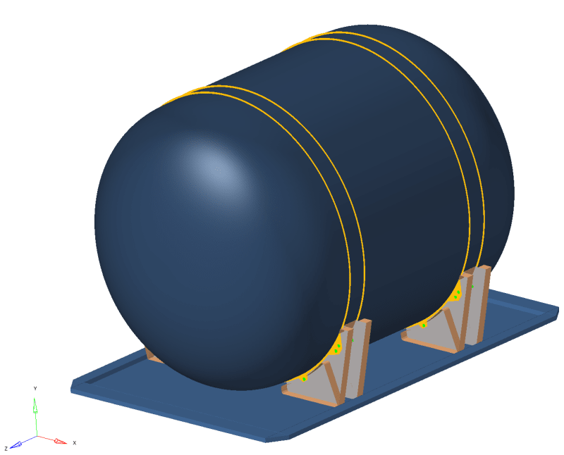
img_ssuip7.png


The glue contact is for the link between the cradles and the base plate, whereas the touch contact is for the cradles/tank contact.
I will also leave attached the .bdf file (in a .zip file given that it has more than 20mb).

Thanks in advance !

Cordially,
EC
 
Replies continue below

Recommended for you

The LINCNT parameter in SOL 101 is a touching contact parameter, and therefore only applies to touching contact, not glue contact, so you may have both types of contact in the job, with or without LINCNT.

The message 8156 you receive is an artefact of the way contact is set up in MSC Nastran. When ALL contact is glue contact, it may be handled internally by the software in a particular way. With the N2S method you are using, this typically means a constraint equation is written for the glue. However, when there is a mixture of glue and touching contact, it is handled not with a constraint equation, but a different method (a Lagrange technique). These 2 methods cannot reside together in the contact definition, so one of the methods must be chosen to handle all contact in the model, both glue and touching. Message 8156 is simply informing you that this has occurred automatically. If you want to force this to happen, as the message hints, you may define NLGLUE=1 on the BCPARA entry. So why bother telling us? Well, permanent glue does what is says on the tin; permanent – it will not change its characteristics. However, when glue contact is changed to NLGLUE=1 contact (called general glue), it simulates permanent glue by using the standard touching contact with a very large separation force. In touching contact, you may define a force (or stress) below which the contact will not separate, but if the contact force is exceeded, the contact separates. If you set this maximum separation force to a very large value, essentially the contact will remain “stuck” together – but what is large? By default, this separation force is set to 1.0E+30 for glue contact treated as general glue. You can modify its value using the FNTOL parameter on BCONPRP if you want to. Be careful though, because FNTOL works hand in hand with IBSEP which defines the method used (force or stress and exactly how the separation condition is to be treated); it is best to leave this alone for the majority of cases.

You asked “Is it normal to not obtain contact outputs when working with glued contacts?”. Contact will only output forces if forces are generated.

I ran your job, and it converges to completion in all 4 SUBCASEs; why do you say it does not converge? The only contact forces I see are at the glue contact. From this, I conclude that the touching contact does not touch at any stage. A quick look at the displaced shape indicates that, for some loading, the large reservoir should touch the cupped supports, but it doesn’t – why? I see you have made the same configuration error you made in the 2 plate example. You are defining LINCNT for the touching contact, but the regions of the parts where the touching should occur are separated by an initial distance which is greater than the sum of half the plate thickness of the 2 parts. If you remember from the 2 plate discussion, LINCNT always refers back to the initial geometry location, and there is no contact possible with the initial geometry. Action: remove the LINCNT parameter from BCPARA, or use a nonlinear solution sequence (where LINCNT does not act). When you do this, you get contact forces between the reservoir and supports.

Finally, I recommend you apply the load in one go with an NLSTEP entry and NINCC=1 on the LCNT line (as I explained in the 2 plate post). Why? If you let the defaults run, the load will be applied in 10 equal increments. This means that computation time will be needed to obtain convergence for partial loading conditions, loading conditions for which there is no output, and for which you have no interest. If you set NINCC=1 on NLSTEP, the full load is applied, and any penetration conditions the contact detects will be resolved by additional iterations, the number of which will generally be fewer than if the total number of iterations needed to resolve all those intermediate loading conditions of no interest. You will get the same final answer, just faster (unless you enjoy waiting for jobs to run).

DG
 
Dear EC,
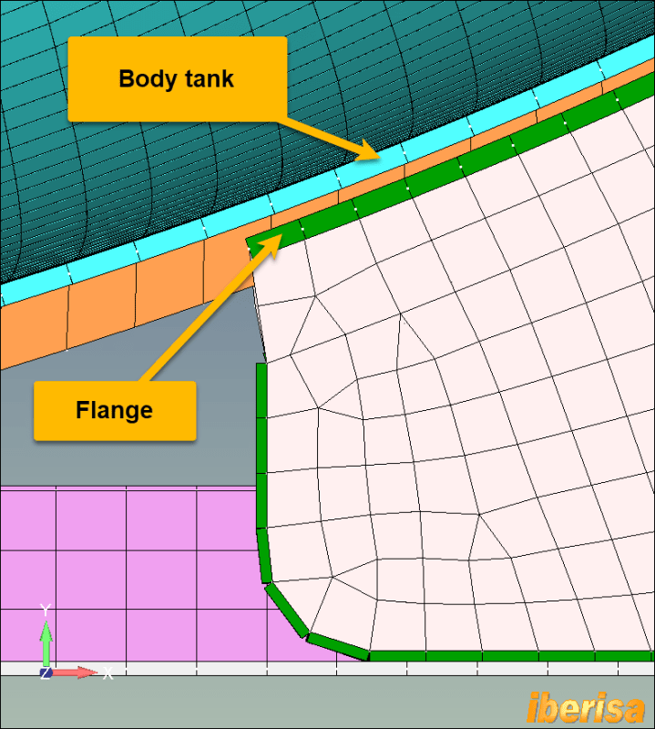
I have loaded your BDF file in FEMAP and I see a critical modeling issue if you plan to solve your model using the Linear Static (SOL101) nastran solver using surface-to-surface contact no penetration: the body tank and the flange bed faces are not touching, you have an important GAP between them. In linear static contact problems all touching faces must be mounted in physical contact, is not correct to let the solver to do the job to move the model, this is large displacements effect and a nonlinear analysis is required.
tank-model-shell-distance_spwz8w.png


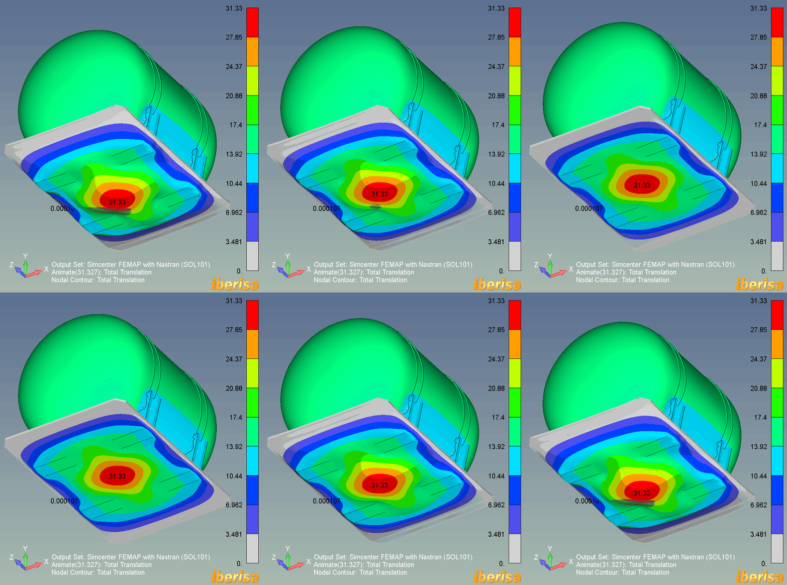
I have solved the model for linear static (SOL101) using the LOAD CASE#5 GRAVITY 12G in vertical direction and I I have set all connectors to have GLUE contact, then not matter the shell faces are not in contact the GLUE connector transmit loadings. The animation of resultant displacemente deformed shape shows big values above 30 mm: for that acceleration the behaviour is totally nonlinear, then a linear static analysis are simply colors (deformed shape exagerated, of course, is only for trending).
tank-ures-animated_ujdqar.gif


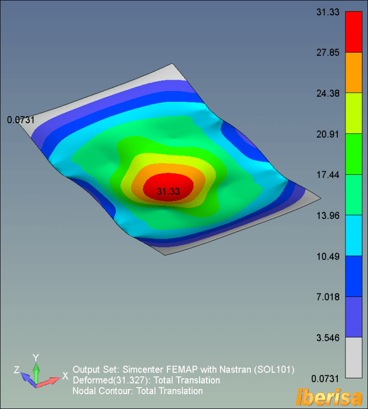
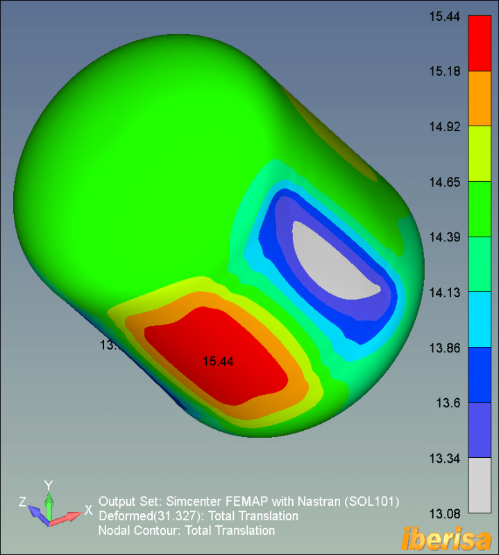
Investigating I see the BASEPLATE is the "guilty", the tank resultant displacement is "only" 15 mm, a big value for a tank thickness = 3 mm (clearly the problem is nonlinear).

tank-base-plate-ures_zbhkcj.png


tank-model-shell-ures_upbv8k.png


If I have to solve the problem at my end I would run Nastran MultiStep Nonlinear solver (SOL401) using sliding glue contact in the connection between tank body and flange beds.
I hope to be of help!.
Best regards,
Blas.

~~~~~~~~~~~~~~~~~~~~~~
Blas Molero Hidalgo
Ingeniero Industrial
Director

IBERISA
48004 BILBAO (SPAIN)
WEB: Blog de FEMAP & NX Nastran:
 
Thank you both very much for your valuable answers !

dmapguru :
Thank you very much for the clarification on the NLGLUE=1 message.

I have run the analysis with the NLSTEP card as you told me. However, I did not find the NINCC parameter directly in HyperMesh, then I defined the NLSTEP entry as follows :

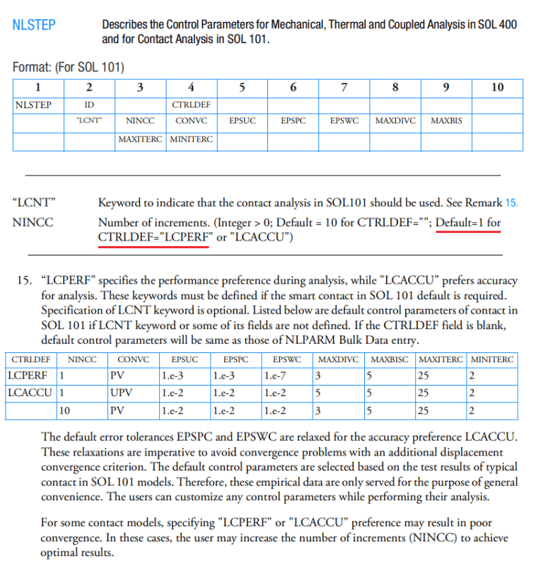
NLSTEP 7 LCPERF

Which according to the QRG sets as default NINCC = 1 for SOL 101 (cf. image below).

QRG_ga1dea.png


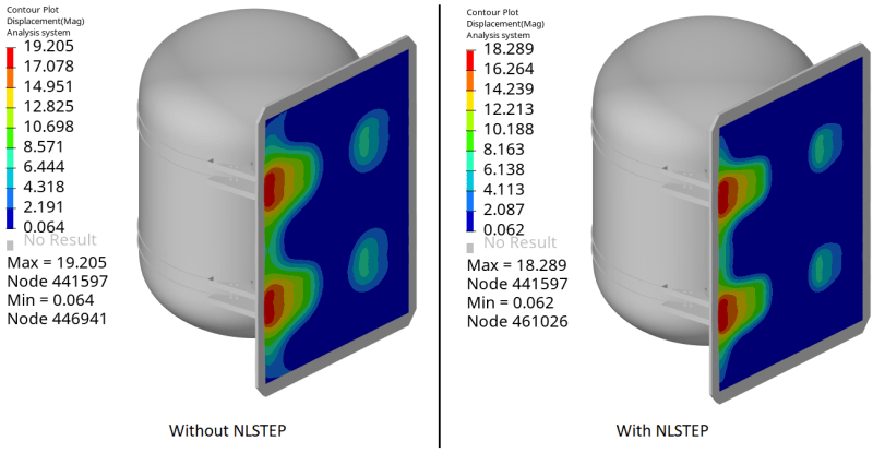
I can constate that the calculation time is noticeably reduced. Nevertheless, I find different results (cf. figure below). Is it normal ?.

Comparison_qx6vyv.png


I leave both .bdf files attached so you can compare if you desire to. I compared both files using Notepad ++ Compare Plugin to verify that NLSTEP entry is the ONLY difference.

On the other hand, I suppressed the LINCNT parameter as you remarked. Thanks again.

BlasMolero :

What you say about the need of a NL analysis is totally true. The problem is that I do not have license for the SOL 400 and SOL 106 does not support contacts.

I have to solve the issue that you remarked about the gap between the tank and the flange. I have not modified it yet because if I move the tank or the cradles I have to redo the pins and their holes. I do not think that using a glue contact between the tank and the cradles is the best idea because if I do that, and I run the 16G load case, all the 4 cradles will be "holding" the tank, whereas in reality it is mostly supported by the 2 cradles that are in the direction of displacement of the tank.


Thanks again to both of you for your help and your time.

Sincerely,
EC

 
Status
Not open for further replies.

Part and Inventory Search

Sponsor